Remote building control data display with automatic updates

a technology of remote monitoring and building control, applied in the field of remote monitoring of building control systems, can solve the problems of time-consuming and inefficient receiving updates over the internet, significant limitations of the type of system described, and large bandwidth and download time, and achieve the effect of convenient updating

Active Publication Date: 2012-04-10
SIEMENS IND INC
View PDF16 Cites 19 Cited by
  • Summary
  • Abstract
  • Description
  • Claims
  • Application Information

AI Technical Summary

Benefits of technology

[0014]The present invention addresses at least some of the above stated needs, as well as others, by providing a remote display update device that employs refresh technology that does not require re-polling by the user. In other words, the device employs a technique that enables server to send data to client without the client having to request it. The technique is based on an event-driven web application that is hosted in the web browser. In one embodiment, a remote alarm graphic system uses web movie technology to provide a remote representation of an alarm graphics display that is easily updated.

Problems solved by technology

There are, however, significant limitations to the type of system described in the '943 patent.
In particular, when building control system information is transmitted in a graphical image context, it requires significant bandwidth and download time.
As a consequence, receiving updates over the Internet can be time consuming and inefficient as compared to receiving updates on a control computer that is connected directly to the building system network.
While ongoing data communication developments improve Internet download speeds, it nevertheless can take significant time to download pages full of graphics.
Moreover, if several clients access the same web server, the large, graphics-intensive downloads may slow the response time of the server, thereby also increasing the delay in receiving graphical build system user interface screens.

Method used


Image

  • Remote building control data display with automatic updates
  • Remote building control data display with automatic updates
  • Remote building control data display with automatic updates

Examples


Embodiment Construction

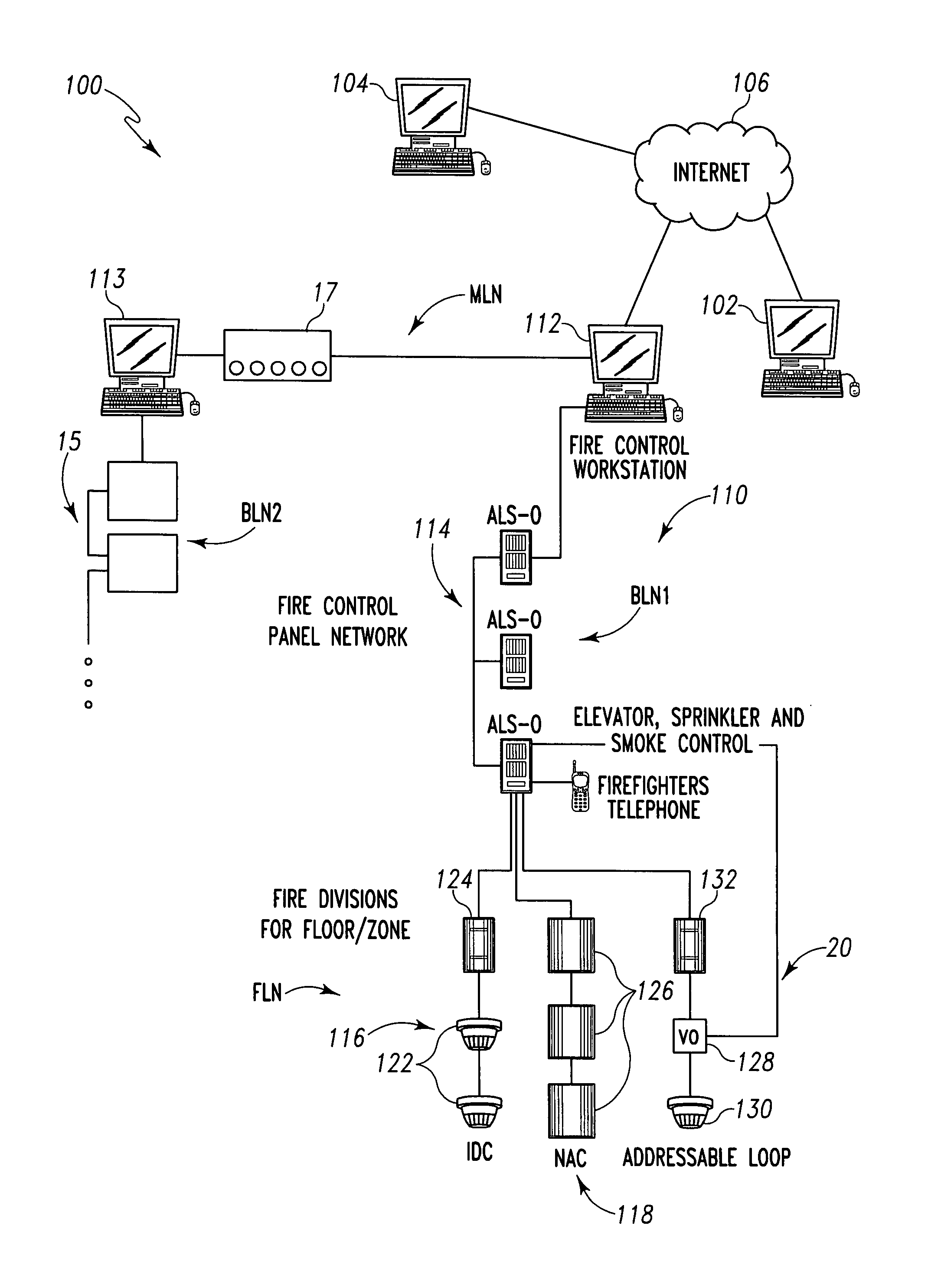
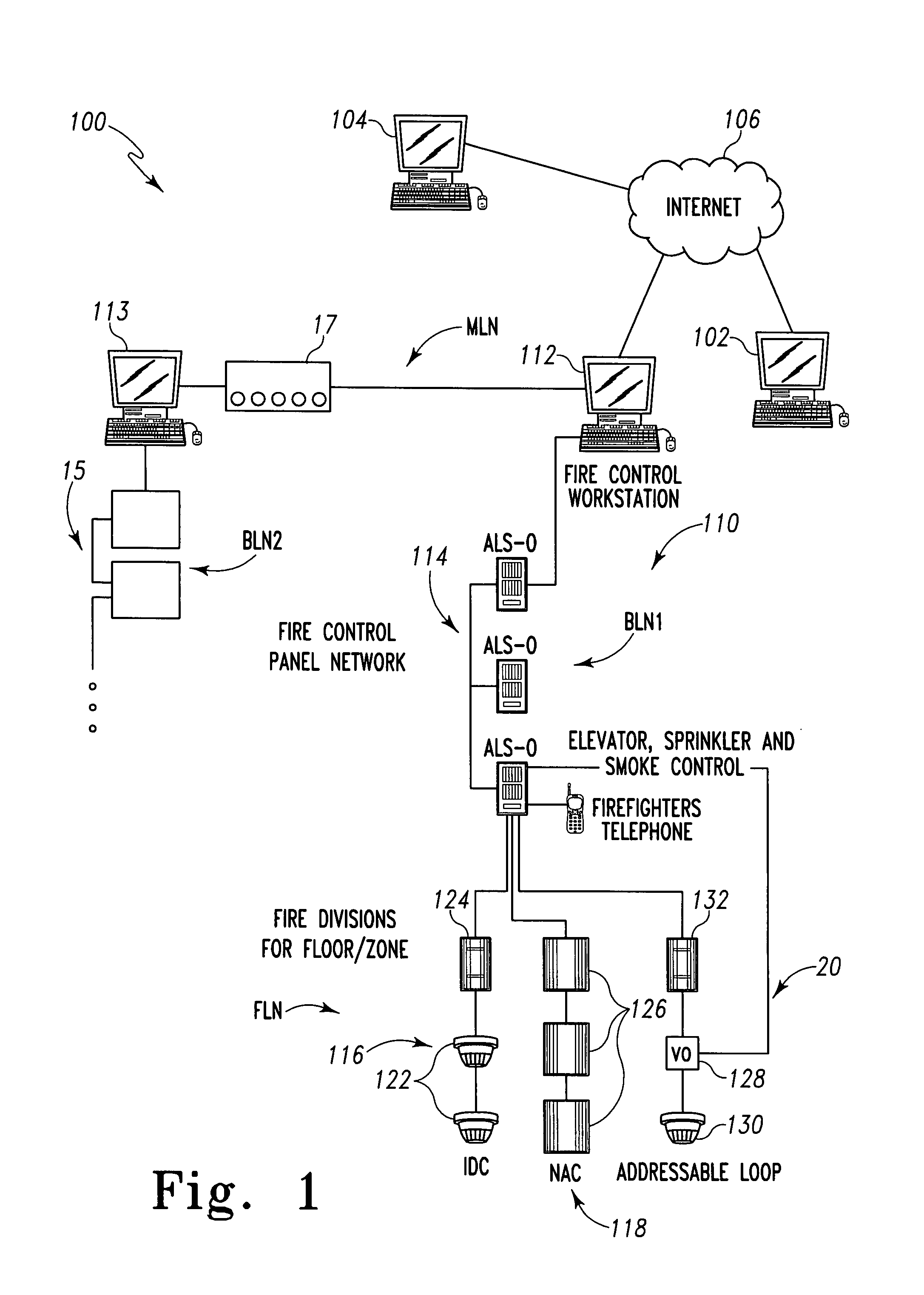
[0024]FIG. 1 shows an exemplary embodiment of a fire safety system 100 in which an embodiment of the invention is implemented. The fire safety system 100 includes a communication network 110 which interconnects fire system devices. The fire system devices of the system 100 include control workstations 112 and 113, fire control panels 114 and 115, and other fire system devices 122, 124, 126, 128, 130 and 132. The other fire system devices include pull stations 124, 132, smoke and / or heat detectors 122, 130, notification appliances 126.

[0025]The network 110 in the embodiment described herein actually involves several layers of interconnected subnetworks, including a management level network MLN, one or more building level network BLN1, BLN2, and one or more floor level networks associated with each building level network. For example, floor level networks 116, 118 and 120 are associated with the BLN1 of FIG. 1.

[0026]The MLN, which may suitably comprise an Ethernet standard network emp...


PUM


Abstract

A method includes receiving at a first computer at least one interpreted program over the Internet using a web-browser. The method further includes executing at the first computer at least one interpreted software program to display at least a first graphical element, each graphical element having characteristics dependent upon a status of a corresponding building control system device in a remote location. The method also includes transmitting to the first computer first information regarding a change in status of at least one building control system device, and then transmitting to the first computer second information regarding a subsequent change in status of at least one building control system device. The transmission of second information is provided in the absence of a request transmitted by the first computer for updated information.

Description

[0001]This application claims the benefit of U.S. Provisional Patent Application Ser. No. 60 / 779,259, filed Mar. 3, 2006, and which is incorporated herein by reference.FIELD OF THE INVENTION[0002]The present invention relates generally to building systems, and more particularly, to remote monitoring of building control systems.BACKGROUND OF THE INVENTION[0003]Building control systems encompass a wide variety of systems that aid in the monitoring and control of various aspects of building operation. Building control systems include security systems, fire safety systems, lighting systems, and heating, ventilation, and air conditioning (“HVAC”) systems. In large commercial and industrial facilities, such systems have an extensive number of elements and are highly automated.[0004]The elements of a building control system are widely dispersed throughout a facility. For example, an HVAC system includes temperature sensors and ventilation damper controls, as well as other elements, which a...

Claims


Application Information

Patent Timeline
Patent Type & Authority Patents(United States)
IPC IPC(8): G06F19/00
CPCG05B15/02G05B2219/2642
Inventor ELMANKABADY, EMADLONTKA, KAREN
Owner SIEMENS IND INC
Why Eureka
Try Eureka