Flash fire and chemical resistant fabric and garments

a technology of fabric and garments, applied in the field of chemical protective clothing, can solve the problems of limited radiant heat resistance of garments, high cost and difficulty in manufacture, and marginal fr

Active Publication Date: 2012-04-17
KAPPLER
View PDF36 Cites 20 Cited by
  • Summary
  • Abstract
  • Description
  • Claims
  • Application Information

AI Technical Summary

Benefits of technology

[0011]An object of this invention is to provide a single fabric material that will provide chemical protection and flash fire protection for use in constructing garments to protect hazardous materials response personnel and chemical plant workers.
[0017]Another embodiment of the use of a clear non flame resistant heat sealable thermoplastic layer of the present invention over a reflective barrier layer. Without being bound by theory or mechanism, this is made possible by the use of a thermal expanding adhesive layer dispersed between the flame retardant fiber and a metalized chemical barrier layer. This thermal expanding adhesive layer prevents ignition of the outer clear thermoplastic layer when exposed to flash fire. In one embodiment, the sealable outermost surface of the outer film layer can be a clear polyurethane film laminated to the metalized barrier film with a tie layer selected from a group consisting of EVA, EMA, and EAA.
[0018]Another embodiment of the present invention is a fabric useful for producing garments and ensembles that provide chemical protection, flash fire protection, and a reduction in radiant heat load that can be readily fabricated into various configurations with heat sealable outer seams.

Problems solved by technology

The single skin standalone suits to meet the requirements of NFPA 1991 were typically made of composites of fluoropolymers that were expensive and difficult to manufacture.
Additionally, these garments offer limited radiant heat resistance as they do not have a reflective surface.
There is an inherent problem with making a clear transparent thermoplastic film flame retardant.
When flame retardant additives are introduced into the film, the result is marginal FR performance and the film becomes milky or cloudy significantly reducing the ability of the reflective surface beneath it to reflect the radiant heat load.
If a non flame retardant clear heat sealable film is used, it will burn off of the surface of the composite when subjected to a vertical flame.
While this fabric provides flame and chemical protection, it is only heat sealable on the inside surface.
This means that the seams of a garment made from this composite can only be heat sealed on the inside of the garment next to the skin.
While the wearer may be protected by the inner seams, undesirable contamination of the fabric substrate could occur through compromised outer seams.
This laminate offers limited chemical resistance and little or no radiant heat resistance.
The disadvantage of this fabric is that it does not contain a reflective layer to block the radiant heat load.

Method used


Image

  • Flash fire and chemical resistant fabric and garments
  • Flash fire and chemical resistant fabric and garments

Examples


example 1

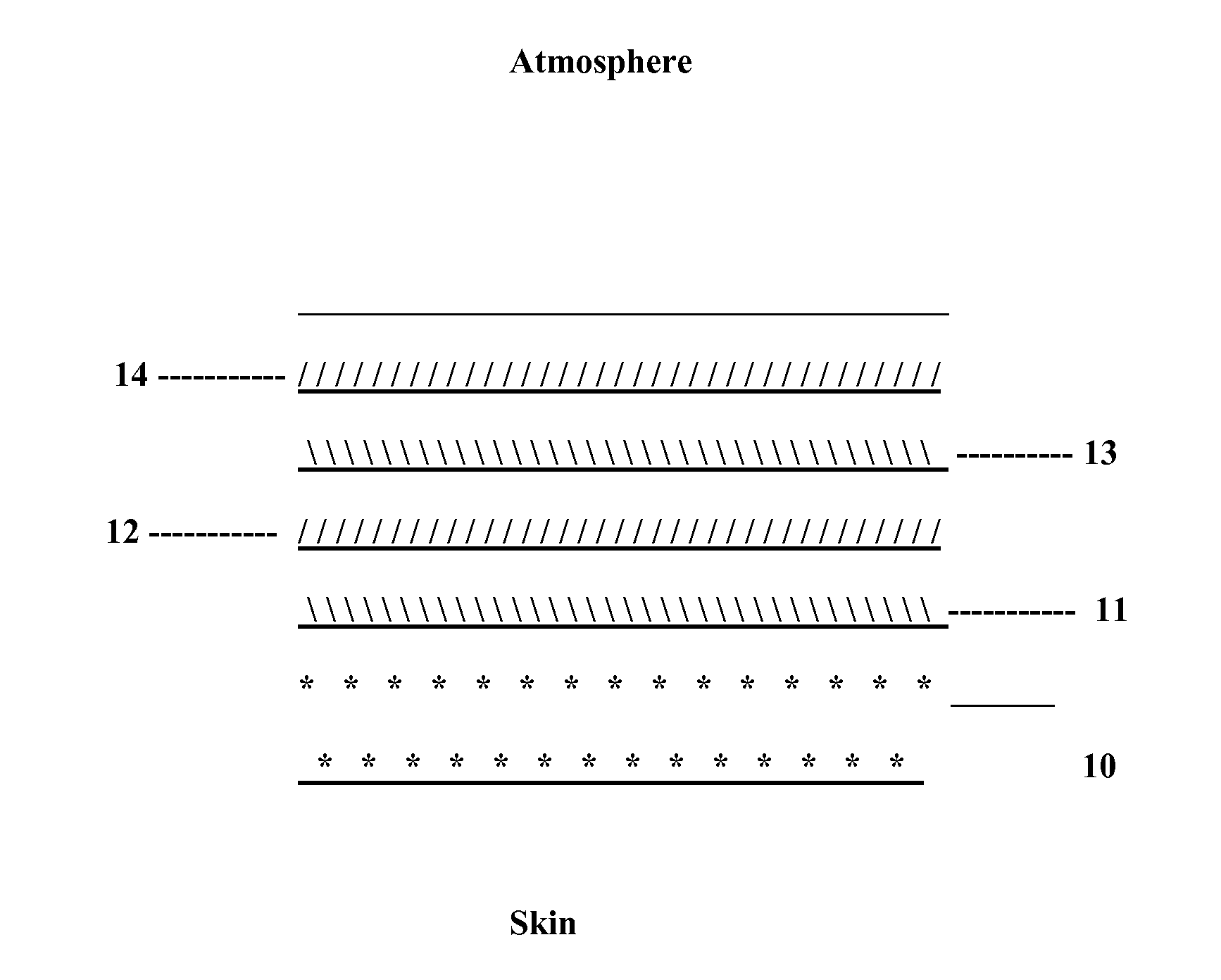
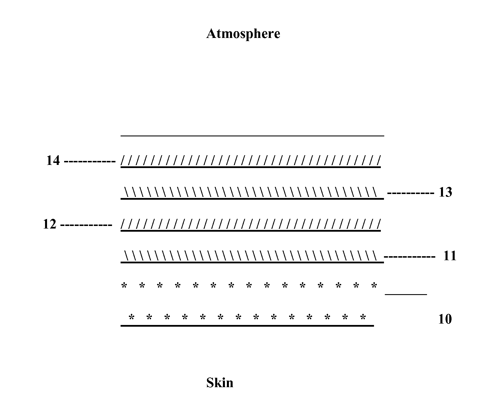
[0049]In a first lamination, a 40 gauge single sided metalized PET film was extrusion laminated to a 1.5 mil cast low density polyethylene film using a co-extruded tie layer of low density polyethylene (LDPE) and ethylene acrylic acid (EAA). The approximate weight of the coextruded tie layer was 18 pounds per ream. This first lamination comprises the chemical and radiant heat barrier component of the composite. The first lamination component was subjected to permeation testing per ASTM F739. This data is presented in Table 1 and Table 2, below.

[0050]The first lamination component was then adhesively laminated to a 8.5 oz / yd2 flame retardant treated cotton terrycloth fabric. A 10 oz / yd2 expanding graphite adhesive was used to accomplish this lamination. Physical properties are summarized in Table 4. The flash fire data in Table 3 for Example 1 indicates only a 16% rise in internal temperature as compared to the exposed metalized surface of the '708 teaching. It can be seen that this ...

example 2

[0052]In a first lamination, a 40 gauge single sided metalized PET film was extrusion laminated to a 1.5 mil cast low density polyethylene film using a co-extruded tie layer of low density polyethylene (LDPE) and ethylene acrylic acid (EAA). The approximate weight of the coextruded tie layer was 18 pounds per ream. This first lamination comprises the chemical and radiant heat barrier component of the composite. The first lamination was then adhesively laminated to a 5 oz / yd2 nonwoven fabric of Basofil fibers. A 10 oz / yd2 expanding graphite adhesive was used to accomplish this lamination. Physical properties are summarized in Table 4.

[0053]Example 2 passed flammability when tested per ASTM F1358 and D6413.

example 3

[0054]In a first lamination, a 40 gauge single sided metalized PET film was extrusion laminated to a 1.5 mil cast low density polyethylene film using a co-extruded tie layer of low density polyethylene (LDPE) and ethylene acrylic acid (EAA). The approximate weight of the coextruded tie layer was 18 pounds per ream. This first lamination comprises the chemical and radiant heat barrier component of the composite. The first lamination component was then adhesively laminated to a 10 oz / yd2 flame retardant treated cotton terry cloth fabric. A 13 oz / yd2 expanding graphite adhesive was used to accomplish this lamination. Physical properties are summarized in Table 4.

[0055]Example 3 passed flammability when tested per ASTM F1358 and D6413.


PUM

PropertyMeasurementUnit
surface temperatureaaaaaaaaaa
heightaaaaaaaaaa
diameteraaaaaaaaaa

Abstract

A flash fire and chemical barrier composite fabric, comprising a flame resistant fibrous basic layer; a radiant heat and chemical permeation barrier, the barrier including a metalized polymeric chemical permeation resistant layer film; and a clear heat sealable outer film layer overlying the radiant barrier and forming a heat sealable outer surface of the composite fabric.

Description

PRIORITY INFORMATION[0001]This application claims benefit to U.S. Patent Application No. 61 / 135,457, filed Jul. 21, 2008, the contents of which are incorporated herein by reference in their entirety.FIELD OF THE INVENTION[0002]The present invention relates to chemical protective clothing and the fabrics used therein. More specifically the present invention relates to chemical protective composite fabrics that also have flash fire resistance.BACKGROUND OF THE INVENTION[0003]Over the last few decades the choices of chemical protective clothing and ensembles available to hazardous materials clean up responders and plant workers have expanded significantly. As awareness of the hazards associated with dangerous and toxic chemicals in the liquid and or vapor forms increased, the chemical protective fabrics began to transition from rubber or PVC based fabrics to the more chemical permeation resistant film based fabrics.[0004]ASTM International (ASTM), originally known as the American Socie...

Claims


Application Information

Patent Timeline
Patent Type & Authority Patents(United States)
IPC IPC(8): A62D5/00A41D27/02A41D31/02
CPCA41D31/0027A62D5/00A41D31/085Y10T442/2631B32B27/12A62B17/006B32B15/14
Inventor TERRELL, ADAM J.
Owner KAPPLER
Why Eureka
Try Eureka