Multiple phase PCM heat insulation blanket

a pcm and blanket technology, applied in the field of multi-phase pcm heat insulation blankets, can solve the problems of reducing the insulation effect of pcm, so as to achieve the effect of a greater insulation benefit for the building structur

Inactive Publication Date: 2012-04-17
ACTIVE INTEGRATION
View PDF8 Cites 33 Cited by
  • Summary
  • Abstract
  • Description
  • Claims
  • Application Information

AI Technical Summary

Benefits of technology

[0015]Another feature of the disclosure is that a sheet of metal foil positioned between the inner and outer sheets of barrier film may be chosen to transfer heat between the pods when the different PCMs of adjacent ones of the pods change temperatures. This provides the blanket the capacity to maintain both of the PCMs at about the same temperatures.
[0018]This disclosure also concerns improving the insulation installed in walls, ceilings and roofs by having multiple PCMs that form a “range” of phase change temperatures. This overcomes the problem that exists when a single PCM has a phase change temperature that falls outside of the temperature cycle. For example, the wintertime temperature cycle favors a lower PCM phase change temperature and the summertime cycle favors a higher PCM temperature phase change. A single PCM may work properly in the winter season, but may be limited or not work at all in the summer season, or vice versa.
[0019]Multiple PCMs therefore can work in a much broader range of conditions and achieve greater insulation benefit for the building structure.
[0023]Preferably, the PCM heat insulation blanket is formed of support sheets that are of heat fusible material, such as polyester and polypropylene. In situations where the fusion of the layers of sheet material is not practical, adhesive bonding of the seams may be possible.

Problems solved by technology

However, the fiberglass alone usually does not provide adequate heat insulation against radiant heat transfer.
This delays the transfer of heat from the warmer interior of the building to the cooler outside atmosphere.
This makes the PCM ineffective to reduce the transfer of heat through the outside wall by changing phase.
This makes the PCM substantially ineffective to insulate the wall structure.
A similar problem may be encountered in the cold season when the outside temperature of the external wall remains so cold that it is not able to change the PCM into its liquid state.
However, if the temperature of the outside surface of the external wall in the warm season does not decrease enough to pass the phase change temperature of the PCM, the PCM does not change phase from liquid to solid and therefore does not have the capacity to change from a solid back to a liquid the next day and insulate the wall structure from the heat of the next day.
Likewise, if the temperature of the outside surface of the external wall in the cold season does not increase enough in the day time hours to pass the phase change temperature of the PCM, the PCM does not change phase from solid to liquid and therefore during the next day there is no liquid PCM available to change back from a liquid to a solid and insulate the wall structure from the heat of the outside surface of the wall structure.
While the foregoing descriptions of how single PCMs may work in an outside wall structure of a building, there are other situations where similar uses of single PCMs would not perform to change phase and therefore not function efficiently to retard the transfer of heat.
However, if the heat source in the room does not raise the temperature of the PCM in the wall to a level higher than its phase change temperature, the system of preserving the room temperature does not work.

Method used


Image

  • Multiple phase PCM heat insulation blanket
  • Multiple phase PCM heat insulation blanket
  • Multiple phase PCM heat insulation blanket

Examples


Embodiment Construction

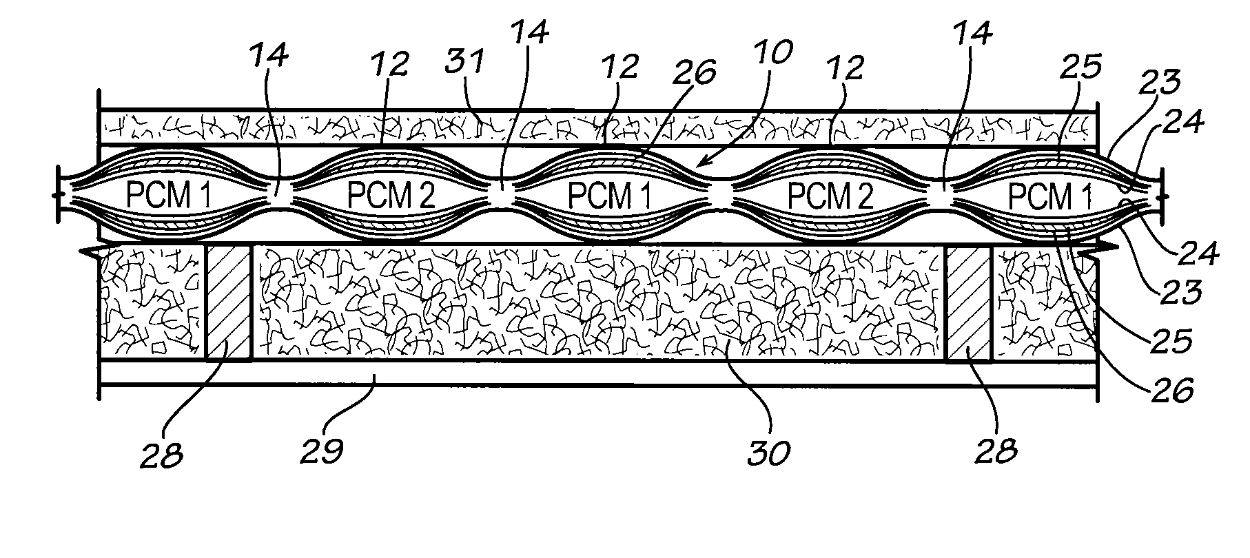
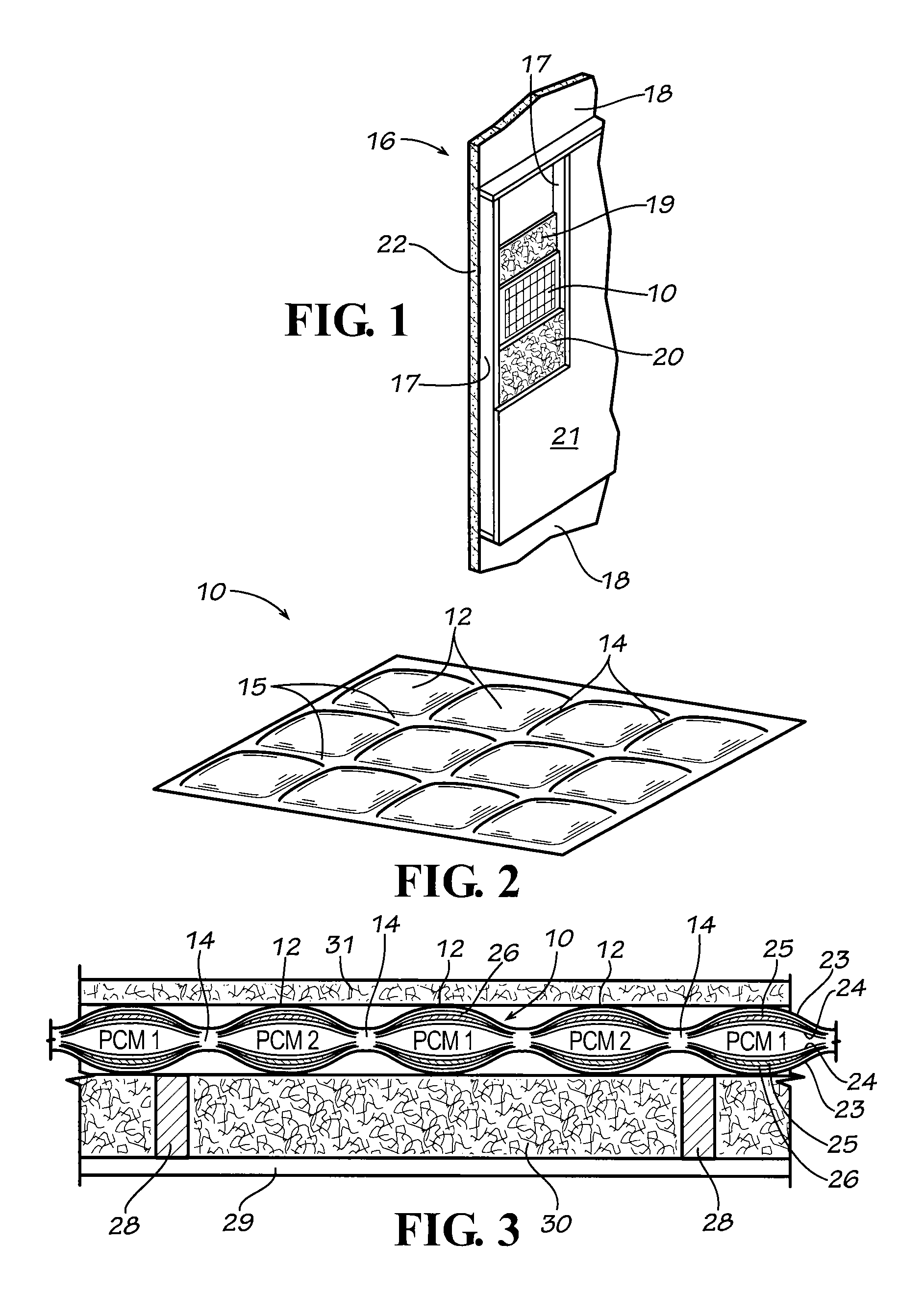
[0035]Referring now in more detail to the drawings, in which like numerals indicate like parts throughout the several views, FIG. 2 illustrates a composite heat insulation blanket or blanket 10 that contains two PCMs that are employed for reducing heat transfer between adjacent spaces about a building structure. The PCM heat insulation blanket 10 includes a series of pods or cells 12 that are formed by heat sealing or bonding layers of thermoplastic material together, with the fused seams 14 intersected by lateral heat fused seams 15.

[0036]As shown in FIG. 1, the PCM heat insulation blanket 10 may be inserted in an external wall structure 16 of a building. Typically, a building will include vertically oriented studs 17 that are spaced apart sixteen inches on center. An exterior board 18 closes the space on the outside between the studs 17. Blanket insulation, such as fiberglass blanket 19, may be installed between the studs next to the exterior board 18, the PCM heat insulation blan...


PUM

PropertyMeasurementUnit
atmospheric temperatureaaaaaaaaaa
temperatureaaaaaaaaaa

Abstract

A PCM heat insulation blanket (10) is positioned in a wall structure of a building for modulating the transfer of heat to and from the controlled internal temperature of the building structure. The PCM heat insulation blanket includes an array of pods (12) with one group of pods 12A containing a first PCM and a second group of pods containing a second PCM 12B having a different phase change temperature than the first group of pods. The pods with different PCMs are substantially uniformly intermixed among each other. The pods are formed of laminated sheets, each of which may include a metal foil that is vapor impermeable and tends to maintain the PCMs in the blanket at approximately the same temperature, and which also functions to reflect radiant heat away from the temperature controlled internal space of the building structure.

Description

FIELD OF THE INVENTION[0001]This invention involves heat insulation in building structures whereby the walls, roof, ceiling, floors and other partitions of the building that separate the temperature controlled interior of the building are insulated from an adjacent area, such as the outside atmosphere or an adjacent space. More particularly, this invention involves a heat insulation structure that utilizes, in various combinations, heat reflective material, dead air space, fibrous blanket material and other heat insulation materials for use alone or in combination with PCM in a building structure, to retard the transfer of heat to or from the temperature controlled interior space. Also, the method of making the heat insulated walls is disclosed.BACKGROUND OF THE DISCLOSURE[0002]Heat insulation material placed in external walls, ceilings, roofs, floors and other areas about a building typically comprise fibrous blanket insulation, such as elongated blankets formed of fiberglass. A pr...

Claims


Application Information

Patent Timeline
Patent Type & Authority Patents(United States)
IPC IPC(8): E04C1/00
CPCB32B3/08B32B3/12B32B15/08E04B1/7654E04B1/78E04B2/707E04B9/001E04B2001/7691F28D20/026F28D2020/0008
Inventor ALDERMAN, ROBERT J.
Owner ACTIVE INTEGRATION
Why Eureka
Try Eureka