Diffusor

a diffusor and exhaust gas technology, applied in the direction of machines/engines, stators, liquid fuel engines, etc., can solve the problems of reducing efficiency, high noise levels at the compressor outlet, and high storage costs, so as to improve the already favorable acoustic properties of the diffusor, reduce the noise of the exit, and the useful characteristic diagram width is greater

Active Publication Date: 2012-04-24
TURBO SYST SWITZERLAND LTD
View PDF8 Cites 37 Cited by
  • Summary
  • Abstract
  • Description
  • Claims
  • Application Information

AI Technical Summary

Benefits of technology

[0012]The set-back of the inlet edge of the hub-side component blade and the associated superposition of the noise fields which are produced on the front and rear inlet edges of the guide blades of the diffusor leads to additional improvement of the already favorable acoustic properties of the diffusors with meridionally tilted guide blades.
[0013]With the stepped diffusor a greater useful characteristic diagram width at the same efficiency and lower exit noise can be achieved than for a meridionally tilted diffusor.
[0014]The thermodynamic performance is likewise improved by a diffusor with meridionally stepped guide blades. While the radially low-momentum flow on the inlet side is guided by the long part of the profile such that the flow assumes the desired direction, on the lift side for a healthy flow (high in radial pulses) a very short diffusor with a large, extremely narrow cross section is used. It is known of diffusors with short guide blades without a meridional tilt or step that they improve the stability of the compressor stage and achieve good efficiencies since the flow-wetted area is small and thus friction losses are low. The improved stability of the flow leads to wider characteristic diagrams. Thus, with one specification a greater bandwidth of engine operating lines which differ in absorption behavior can be accommodated. In this way the number of required specifications is minimized and thus the storage costs can be reduced.
[0015]Moreover, compared to the meridionally tilted guide blades, for the guide blades made stepped with component blades of varied length there are advantages in production. In this case advantageously first of all the guide blade profile is produced as a prismatic profile and then a smaller, likewise prismatic profile is reworked out of the hub-side part at a constant height. This reduces the production cost compared to a meridionally tilted diffusor.

Problems solved by technology

According to experience, the compressor stages with high specific absorption capacities also produce high noise levels at the compressor outlet which are caused essentially by the impact of the flow fluctuations over time on the guide blades of the guide device of the diffusor.
If the characteristic diagrams are narrow, numerous specifications with different blade heights and / or diffusors for matching to the varied application must be observed; this leads to high storage costs.
But both measures lead to a reduction in efficiency, for which reason the desired thermodynamic performance would be missed.
When using meridionally tilted guide blades in the guide device of the diffusors at high absorption capacities strict acoustic requirements cannot be met under certain circumstances.
Production of diffusors with meridionally tilted guide blades is moreover much more complex than that of prismatic blades.

Method used


Image

  • Diffusor
  • Diffusor
  • Diffusor

Examples


Embodiment Construction

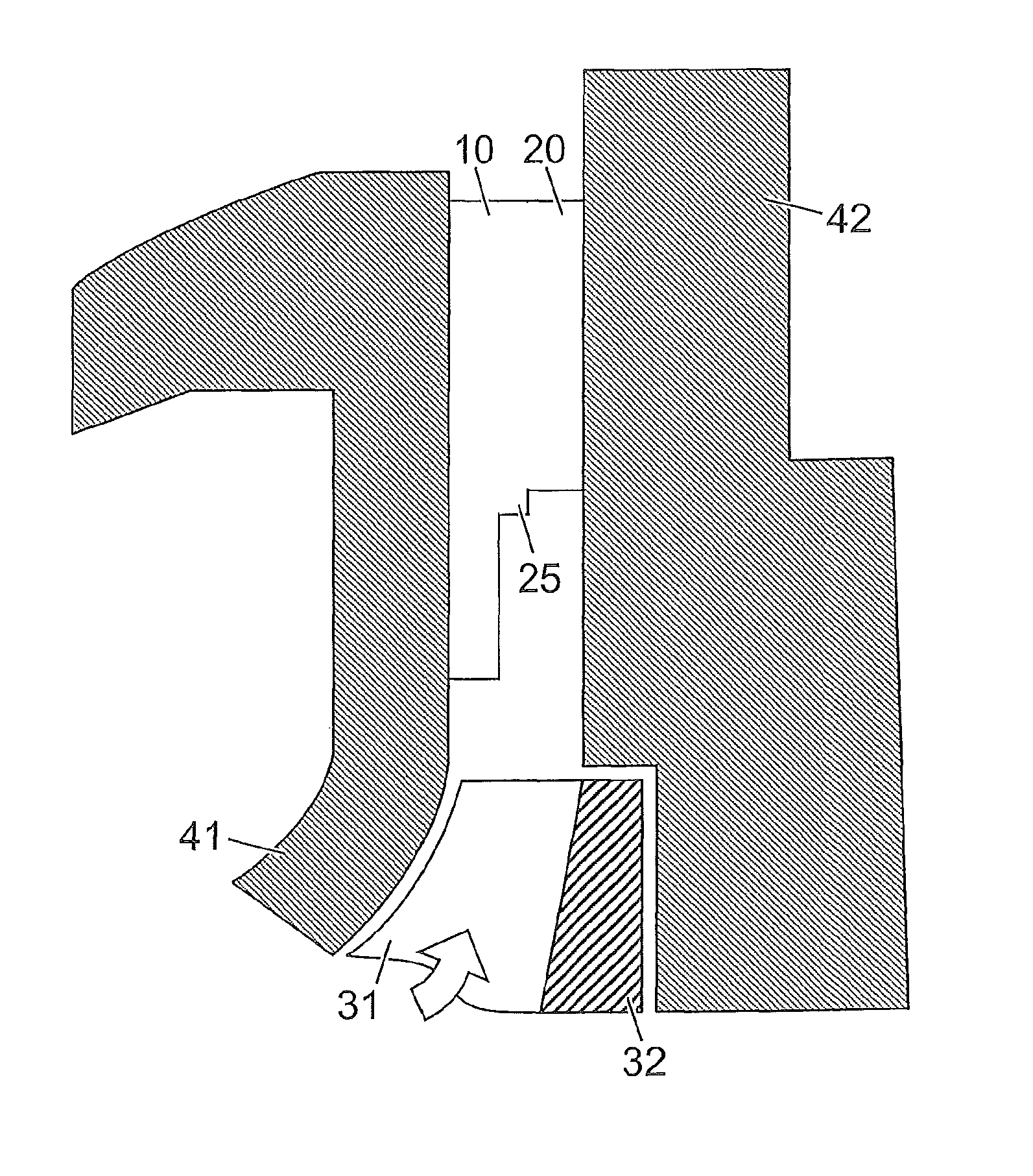
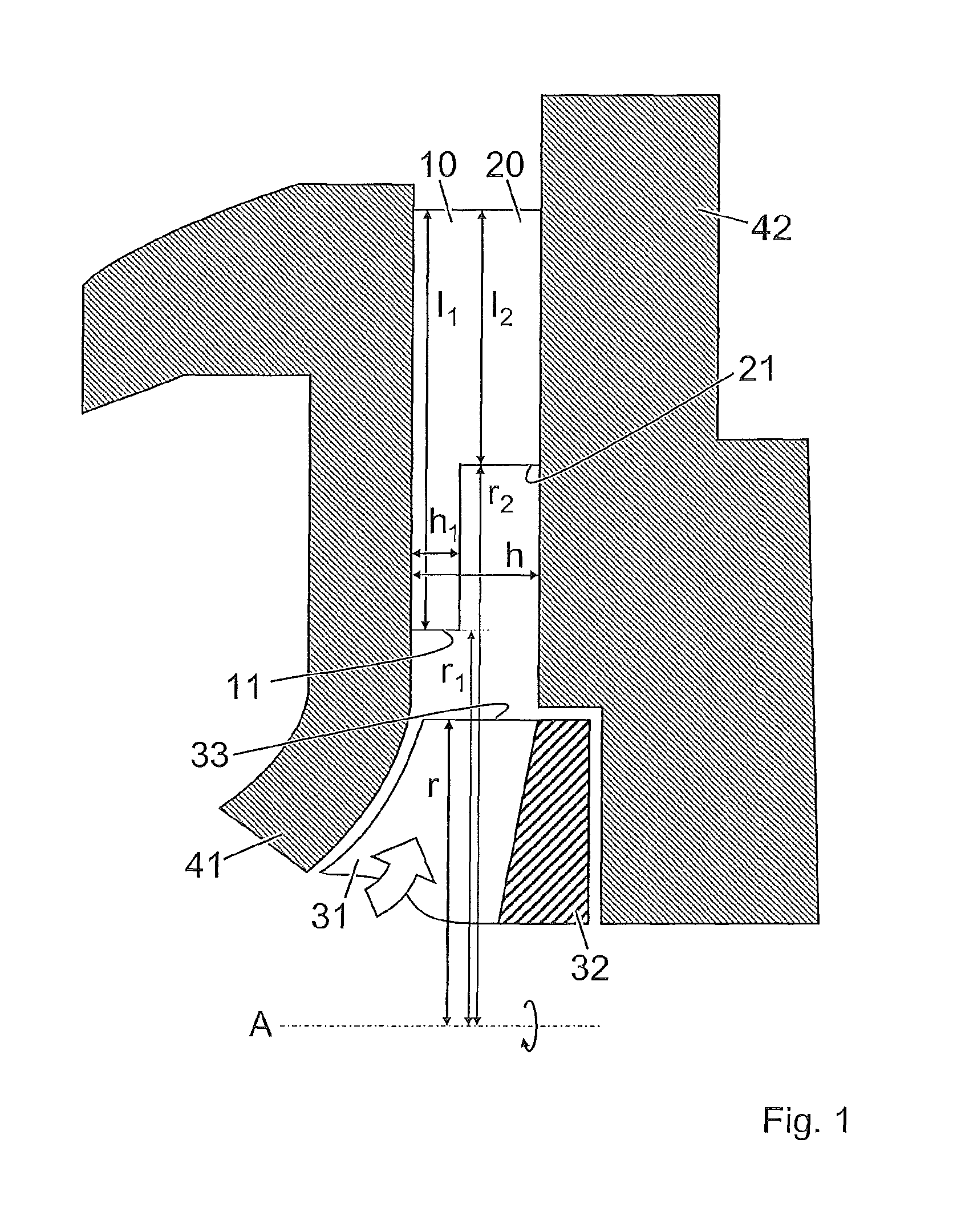
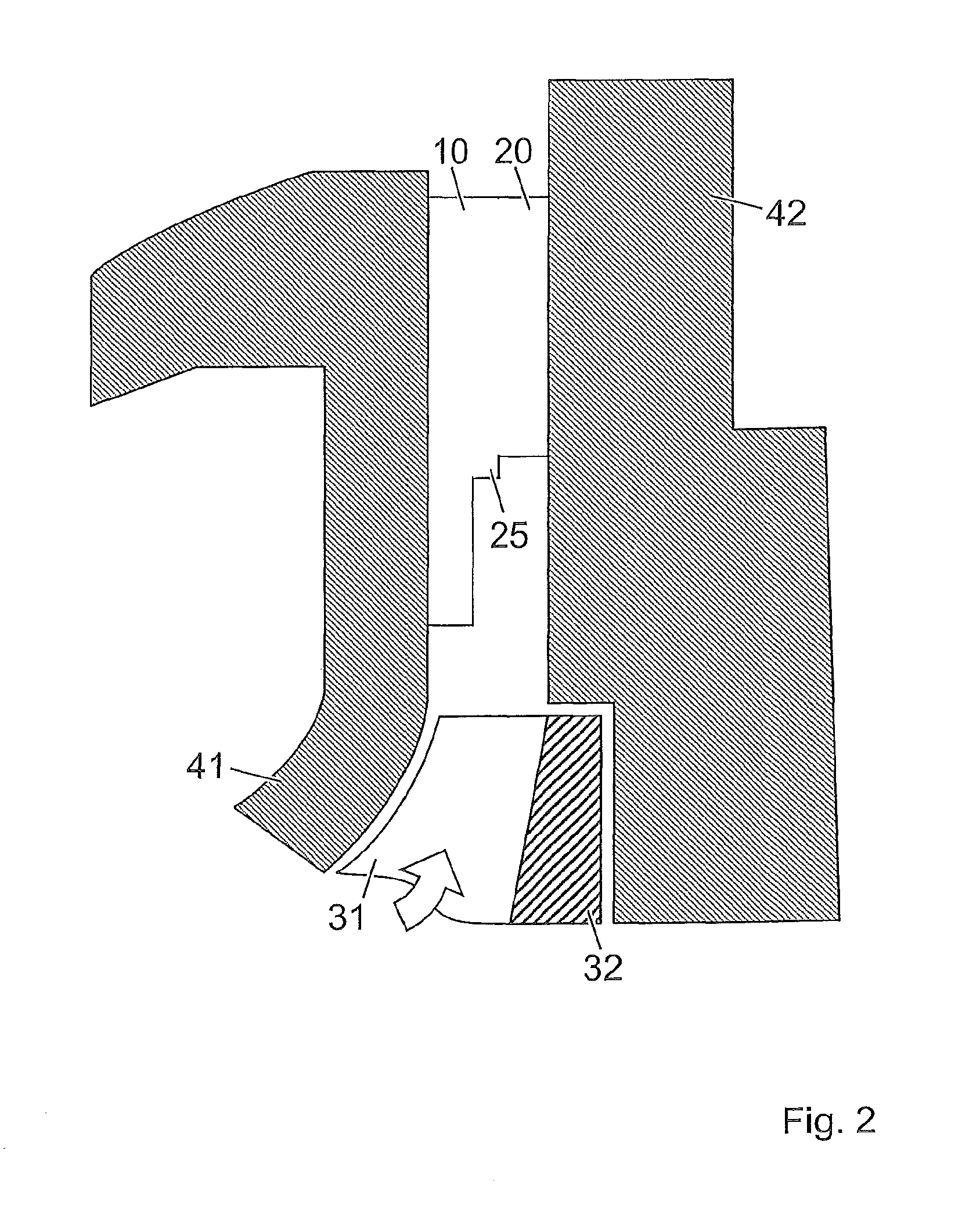
[0021]In a compressor housing which is shown only partially in FIG. 1, a compressor impeller is arranged to be able to turn around an axis A. The compressor housing is schematically comprised of an inlet side housing part 41 and a hub-side housing part 42. The compressor impeller sits on a shaft which for an exhaust gas turbocharger is driven by a turbine which is not shown. The compressor impeller surrounds the hub 32 and, located on the hub, a host of guide blades 31. They extend from the incident flow-side end of the compressor impeller as far as the outflow-side end on the radial outside edge of the compressor impeller. The flow direction is indicated with a thick arrow.

[0022]In the flow direction farther downstream of the outflow-side end of the compressor impeller, there is a diffusor. The diffusor is comprised of the diffusor walls and a guide device with several guide blades located distributed along the periphery. The diffusor walls border the flow channel downstream of the...


PUM


Abstract

The guide device for the diffusor at the compressor impeller outlet of a radial compressor has guide blades with stepped inlet edges. The step is implemented by setting back the hub-side inlet edge. This meridional stepping divides the guide blades into two component blades, of which the first component blade is made longer than the second component blade. The set-back of the inlet edge of the hub-side component blade and the associated superposition of the noise fields which are produced on the front and rear inlet edge of the diffusor leads to improvement of the acoustic properties of the compressor.

Description

RELATED APPLICATIONS[0001]This application claims priority under 35 U.S.C. §119 to EP Application 06405234.3 filed in Europe on May 26, 2006, the entire contents of which are hereby incorporated by reference in their entireties.TECHNICAL FIELD[0002]The disclosure relates to the field of compressors of exhaust gas turbochargers for supercharged internal combustion engines. It relates to a guide device for the diffusor on the compressor impeller outlet of a radial compressor and a compressor with this guide device.BACKGROUND INFORMATION[0003]In modern exhaust gas turbochargers, to increase the intake pressure of internal combustion engines, single-stage radial compressors with bladed diffusors at the compressor impeller outlet are generally used. The diffusors have a guide device with guide blades with prismatic, generally aerodynamic profiles. The outflow of the compressor impeller is hallmarked essentially by a so-called jet wake flow in which radially low-momentum flow collects on ...

Claims


Application Information

Patent Timeline
Patent Type & Authority Patents(United States)
IPC IPC(8): F04D29/30
CPCF01D5/141F01D9/041F02C3/08F04D29/444F05D2220/40F05D2250/52F04D29/44F01D5/14F02C6/12
Inventor KUEHNEL JANPETERFELD HEINZ-J{DOT OVER (U)}RGENLINDBLOM CHRISTINE
Owner TURBO SYST SWITZERLAND LTD
Why Eureka
Try Eureka