Environment control device, environment control method, environment control program, and environment control system

a technology of environment control and control method, applied in the direction of heating type, instrument, static/dynamic balance measurement, etc., can solve the problems of air-conditioning system not performing proper air-conditioning control, user a feeling of discomfort, user b feeling uncomfortable,

Active Publication Date: 2012-04-24
PANASONIC CORP
View PDF27 Cites 3 Cited by
  • Summary
  • Abstract
  • Description
  • Claims
  • Application Information

AI Technical Summary

Benefits of technology

[0009]In view of the conventional examples, an object of the present invention is to provide an environment control device, an environment control method, an environment control program, and an environment control system that enable to estimate amenity of living bodies, considering individual differences in biological information, in the case where the living bodies stay or reside in a common space, and properly control stimulation contents based on the estimated amenity.

Problems solved by technology

In other words, since patent document 1 does not consider individual differences in the absolute value of the pulse wave amplitude, the air-conditioning system may overcool the room despite that the user A feels “moderately cool”, thereby making the user A feel uncomfortable.
In other words, since patent document 2 does not consider individual differences in the correlation between the temperature of the user's back portion and the user's thermal sensation, the air-conditioning system may suspend the cooling operation despite that the user B does not feel hot or cold, thereby making the user B feel uncomfortable.
However, since the thermal sensations of the users are estimated, without considering individual differences in the correlation between the temperature of the user's back portion and the user's thermal sensation, even with use of the average thermal sensation, the air-conditioning system may fail to perform proper air-conditioning control, considering thermal sensations of the users.Patent document 1: Japanese Patent No. 2,833,082 (pp.

Method used


Image

  • Environment control device, environment control method, environment control program, and environment control system
  • Environment control device, environment control method, environment control program, and environment control system
  • Environment control device, environment control method, environment control program, and environment control system

Examples


first embodiment

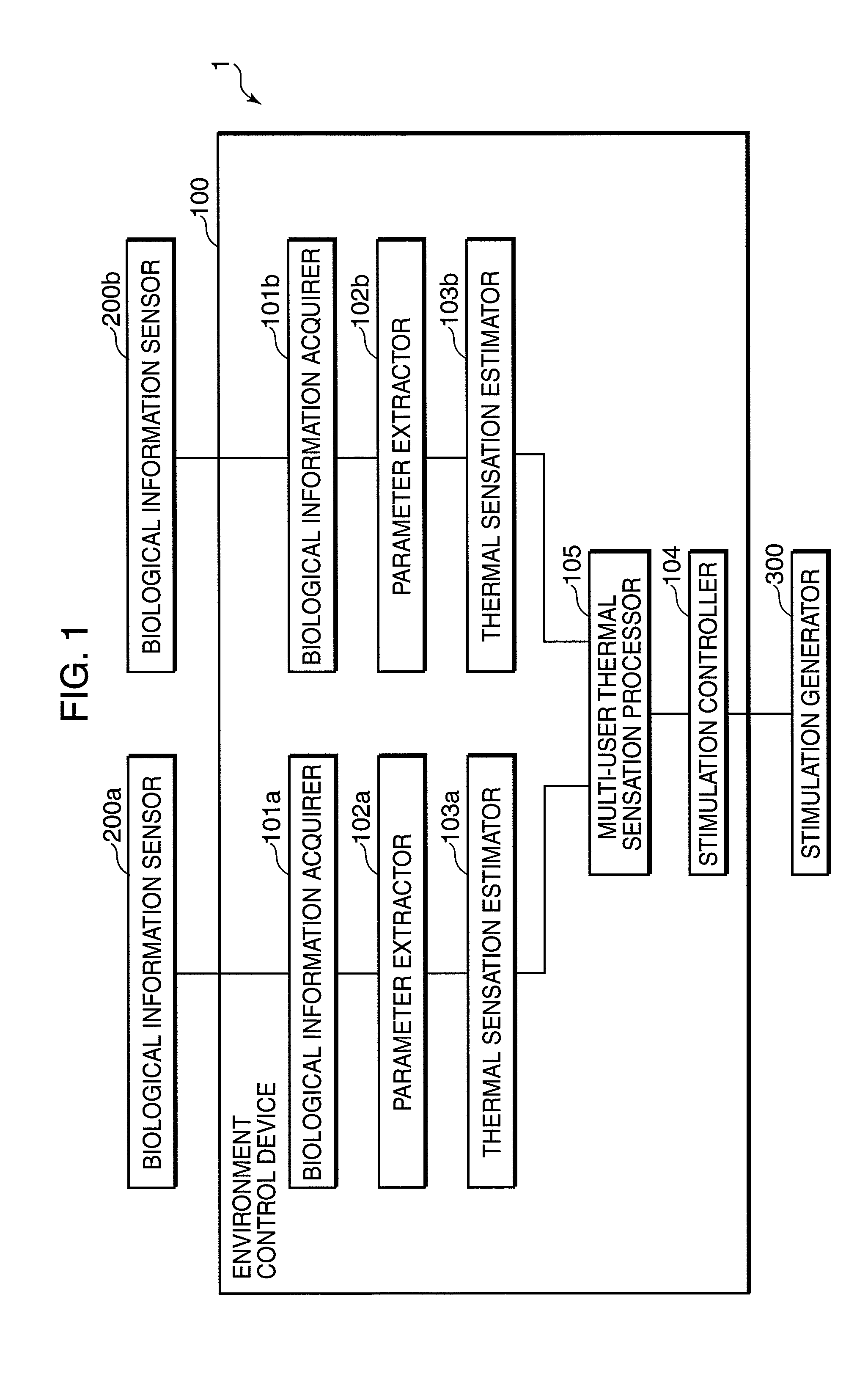
[0033]FIG. 1 is a block diagram showing a configuration of an environment control system in the first embodiment of the invention. Referring to FIG. 1, an environment control system 1 includes an environment control device 100, biological information sensors 200a and 200b, and a stimulation generator 300.

[0034]The biological information sensor 200a, 200b is adapted to measure biological information on each of living bodies. Specifically, the biological information sensor 200a, 200b is a pulse wave sensor, and is configured in such a manner that near infrared light is emitted from a light emitter toward a skin surface of a user's finger or earlobe, transmitted light through the skin or reflected light on the skin is detected by a light detector, and a change in the detected light is converted into an electric signal to detect a change in the blood flow rate, whereby the pulse wave of the user is measured. The stimulation generator 300 generates thermal stimulations to be applied to u...

second embodiment

[0073]FIG. 9 is a block diagram showing a configuration of an environment control system in the second embodiment of the invention. In FIG. 9, constituent elements identical to those in FIG. 1 are indicated with the same reference numerals, and description thereof is omitted herein.

[0074]Referring to FIG. 9, an environment control device 100 additionally includes status continuation time measurers 107a and 107b. Upon receiving an estimation result (indicating that the thermal sensation is shifted from a cold condition to a neutral condition (0), or from a hot condition to a neutral condition (0), or from a neutral condition (0) to a cold condition, or from a neutral condition (0) to a hot condition) from a thermal sensation estimator 103a, 103b, the status continuation time measurer 107a, 107b measures a time when an identical estimation result among the above estimation results is continuously outputted to output a status continuation time indicating the measured time when the iden...

third embodiment

[0090]FIG. 13 is a block diagram showing a configuration of an environment control system in the third embodiment of the invention. In FIG. 13, constituent elements identical to those in FIG. 1 are indicated with the same reference numerals, and description thereof is omitted herein.

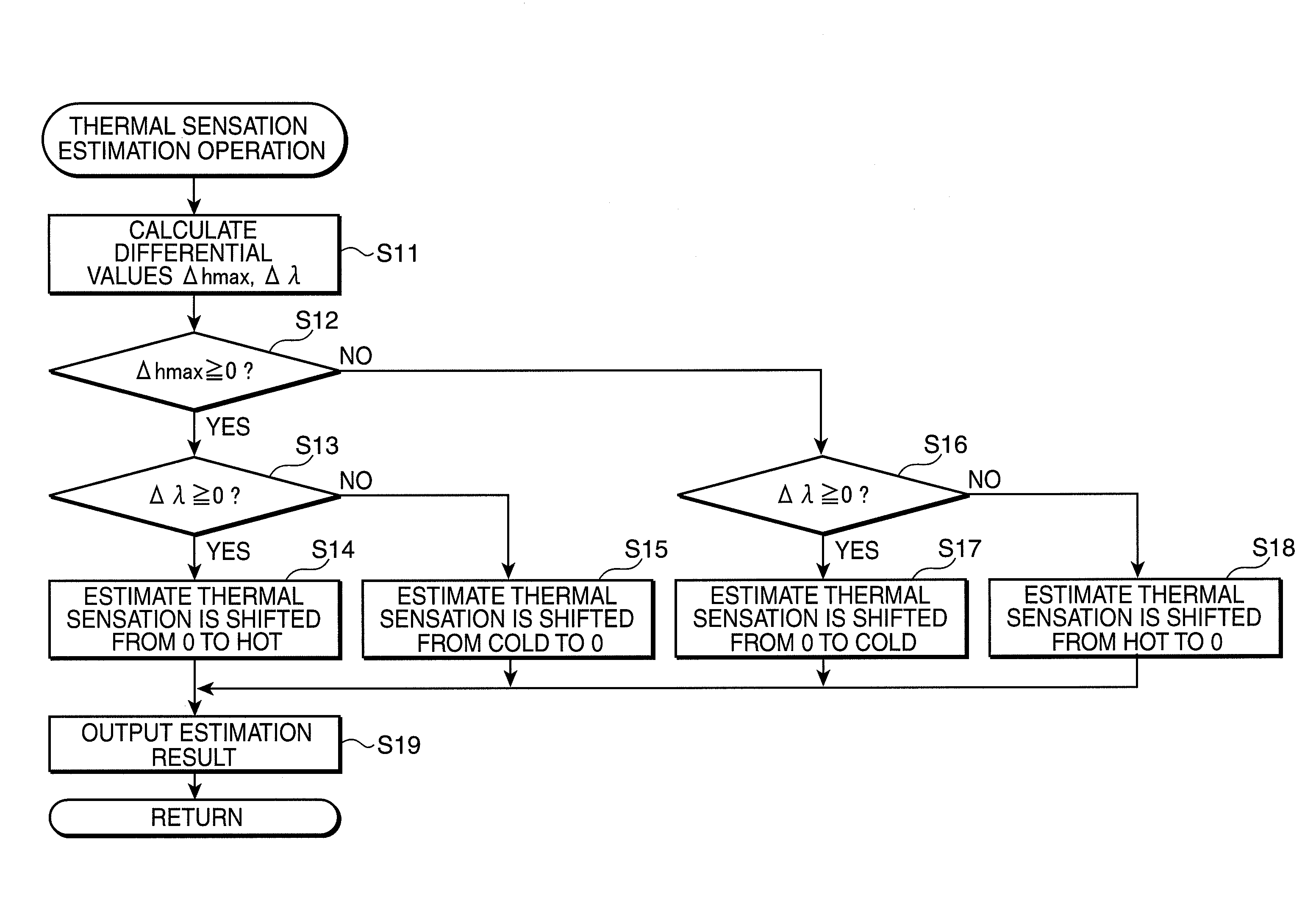
[0091]Referring to FIG. 13, an environment control device 100 additionally includes thermal sensation estimation data judgers 108a and 108b, and status change parameter storages 109a and 109b. The thermal sensation estimation data judger 108a, 108b judges whether the user's thermal sensation has shifted from a hot condition to a neutral condition (0) and then to a cold condition, or from a cold condition to a neutral condition (0) and then to a hot condition, based on user's thermal sensation estimation data from a thermal sensation estimator 103a, 103b, and thermal sensation estimation data which is obtained by a previous estimation stored in the status change parameter storage 109a, 109b.

[0092]The sta...


PUM


Abstract

Comfortable sensation of living bodies is estimated, considering individual differences in biological information on the living bodies staying or residing in a common space, and stimulation contents is properly controlled. A stimulation generator generates a stimulation to be applied to users. Biological information acquirers and acquire time-series data of biological information on the users. Parameter extractors and extract a parameter which is changed with a lapse of time by analyzing the time-series data. Thermal sensation estimators and estimate statuses of the users to the stimulation generated by the stimulation generator, based on the parameter extracted by the parameter extractors and. A multi-user thermal sensation processor integrates estimation results on the users estimated by the thermal sensation estimators and into a single estimation result. A stimulation controller controls the stimulation generator based on the integrated estimation result.

Description

TECHNICAL FIELD[0001]The present invention relates to an environment control device, an environment control method, an environment control program, and an environment control system for estimating the status of a living body based on biological information to control a residential environment.BACKGROUND ART[0002]Heretofore, in controlling a residential environment of the user, an environment control system has been controlled by detecting environmental physical quantities such as a temperature (hereinafter, called as “room temperature”) of the residential environment, a humidity (hereinafter, called as “humidity”) of the residential environment, a temperature (hereinafter, called as “external temperature”) outside the residential environment, and the amount of insolation. Other than the aforementioned control based on the environmental physical quantities, there is proposed an approach of acquiring and analyzing biological information on the user, estimating the status of the user s...

Claims


Application Information

Patent Timeline
Patent Type & Authority Patents(United States)
IPC IPC(8): A61B5/02G06F19/00G06G7/70A61B5/04
CPCF24F11/006F24F11/0017F24F2011/0064Y02B30/78F24F11/30F24F2110/50F24F11/62F24F11/65Y02B30/70F24F11/46F24F11/67F24F2120/20F24F2120/12
Inventor FUNAKURA, MASAMIKANAI, ETSUKOMAEDA, YASUTAKA
Owner PANASONIC CORP
Why Eureka
Try Eureka