
System for contact less data and power transmission

a technology of power transmission and contactless data, which is applied in the field of contactless data and power transmission systems, can solve the problems of increasing construction effort and weight, increasing weight, and affecting passenger convenience, and achieves the effect of reducing or completely eliminating, and light in weigh

Active Publication Date: 2012-04-24
AIRBUS OPERATIONS GMBH
View PDF23 Cites 10 Cited by
  • Summary
  • Abstract
  • Description
  • Claims
  • Application Information

AI Technical Summary

Benefits of technology

The invention is a system for contactless transmission of electrical power and data between vehicle components using a single combination of primary and secondary windings. The system is designed to be simple, lightweight, and cost-effective. The primary winding is connected to the voltage input port of a control unit, while the secondary winding is connected to the data input port of the control unit. The control unit generates an alternating voltage with a frequency modulation based on the data to be transmitted, which is then transmitted through the primary winding to the secondary winding in a second control unit. The secondary winding in the second control unit demodulates the frequency-modulated alternating voltage and provides it for further use. The system can be used in vehicles to simultaneously transmit both electrical power and data without the need for multiple electromagnetic transducers, which reduces weight and costs. The primary and secondary windings can be positioned in various ways within the vehicle, such as on the floor or in vehicle seats, to provide a uniform surface and reduce the need for expensive covers. The system also allows for the simultaneous transmission of power and data using a single combination of primary and secondary windings.

Problems solved by technology

Furthermore, due to sealing requirements between the passenger compartment and the freight compartment, cable infeed routes to the seats through the floor panel of the cabin floor by means of cut-outs or drill holes may only be implemented with increased construction effort and weight.
While it is possible to provide covered cable infeed routes by way of cable ducts on the floor, they are, however, associated with a disadvantage in that each cable duct forms a small uneven area, and consequently passenger convenience may be limited to a significant extent.
This is also associated with increased weight.
Generally speaking this problem relating to the flexible reconfigurability is not limited to variable cabling of passenger seats in an aircraft, but instead extends to every imaginable vehicle component.
However, an arrangement designed in this way is associated with a disadvantage in that all the supply signals and the electrical power need to be transmitted separately from each other.
This is disadvantageous for reasons of weight and cost, in particular if a very large number of passenger seats or other vehicle components need to be equipped with such arrangements for contactless signal transmission.
However, this proposed system, too, does not provide for any coupling between the transmission of electrical power and of data.

Method used


Image

  • System for contact less data and power transmission
  • System for contact less data and power transmission
  • System for contact less data and power transmission

Examples


Embodiment Construction

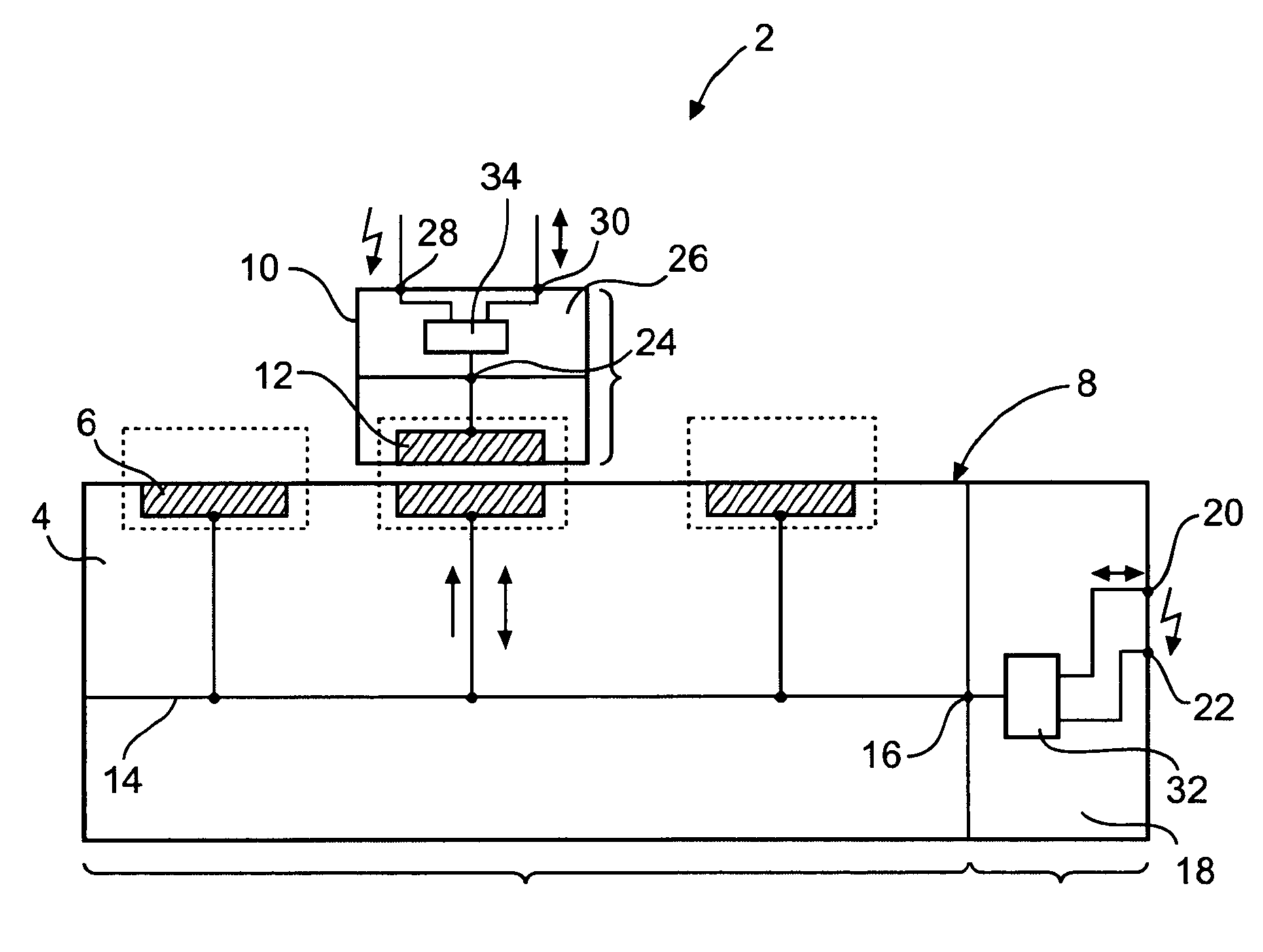
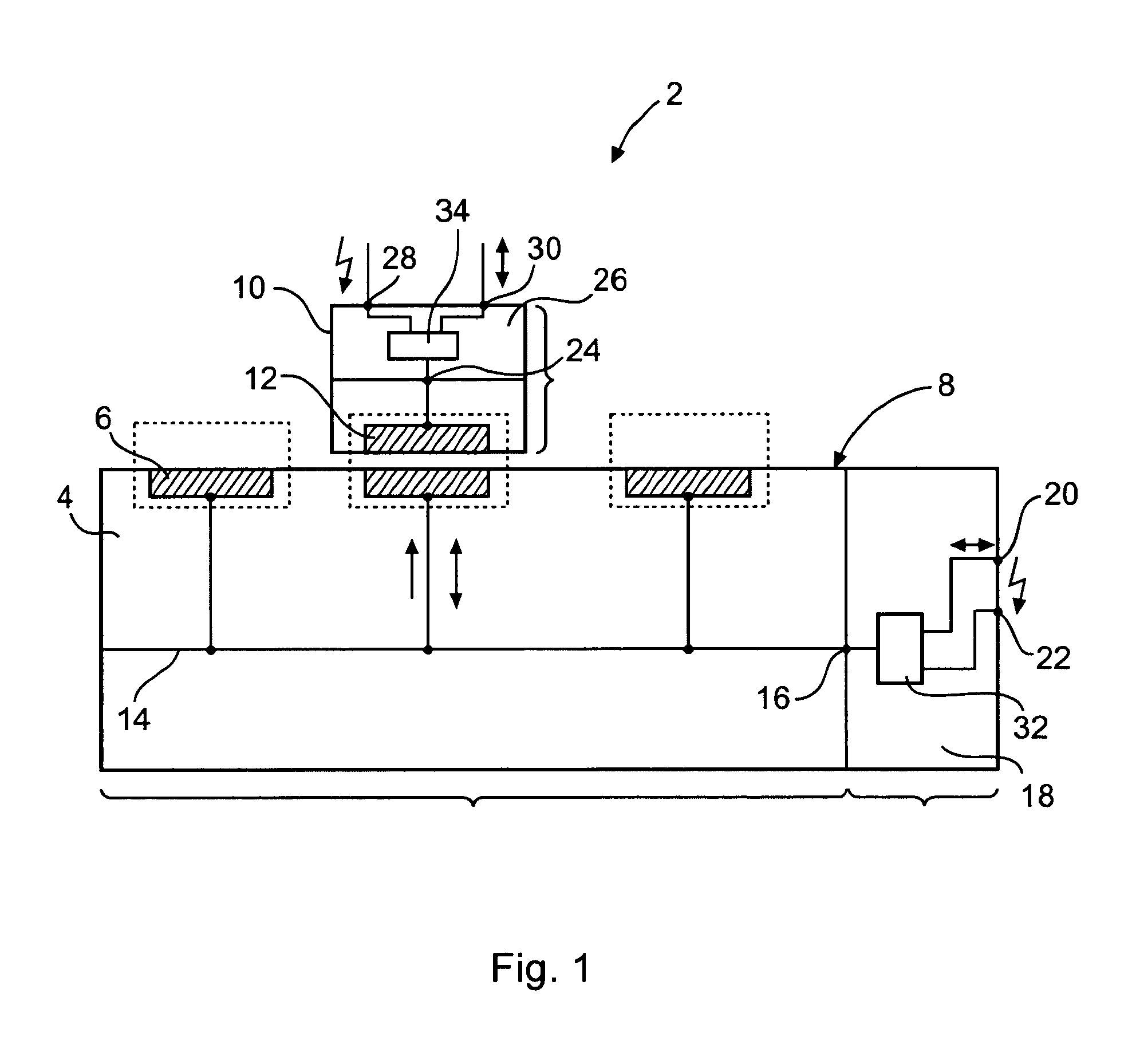
[0022]FIG. 1 shows a diagrammatic view of the system 2 according to the invention. In a first vehicle component 4, for example three primary elements 6 are arranged on a surface 8 above which a second vehicle component 10 with a secondary element 12 may be positioned. In order to establish a connection for the transmission of electrical power and data it is necessary for a magnetic circuit to form between the secondary element 12 and one of the primary elements 6, for example with the middle one of the three primary elements 6, as indicated by a dashed line.

[0023]In each case the primary elements 6 and the secondary element 12 have a core that comprises windings. The winding of a primary element 6 is designated a “primary winding”, while the winding of a secondary element 12 is designated a “secondary winding”. The primary windings of the primary elements 6 are connected to the line 14 which in turn is connected to a signal output port 16 of a first control unit 18. It should be not...


PUM


Abstract

A system for contactless data and power transmission between a first vehicle component and a second vehicle component includes a first control unit, a second control unit, and a transducer with a primary winding and a secondary winding. The first control unit is adapted to generate an alternating voltage at a signal output port from a voltage present at a voltage input port, where the frequency of the alternating voltage is modulated depending on the data that is input at a data input port, and wherein the second control unit is adapted to demodulate the data and provide it at the data output port.

Description

CROSS-REFERENCE TO RELATED APPLICATIONS[0001]This application claims the benefit of the filing date of U.S. Provisional Patent Application No. 61 / 128,090 filed May 19, 2008, the disclosure of which is hereby incorporated herein by reference.BACKGROUND OF THE INVENTION[0002]The invention relates to a system for contactless data- and power transmission between a first vehicle component and a second vehicle component.[0003]In order to provide as flexible as possible a reconfigurability of a cabin of a vehicle that comprises, for example, a modular seating concept with seats that may be affixed in various positions, it has to be possible to electrically couple, to fixed vehicle components, the electrical and electronic devices that are usually located in the seats in all the provided seating positions in the cabin. For example, in a passenger cabin of a modern commercial aircraft it is necessary to provide a very large number of passenger seats or passenger seat groups with electrical c...

Claims


Application Information

Patent Timeline
Patent Type & Authority Patents(United States)
IPC IPC(8): B60L1/00
CPCB60R16/027H02J5/005B64D11/0624H04L27/10H04L25/02B64D11/06Y10T307/297H02J2310/44H02J50/70H02J50/10
Inventor BAUER, HANS-ACHIMZYBALA, ANDRE
Owner AIRBUS OPERATIONS GMBH
Learn More