Four pad self-calibrating electronic lapping guide

Inactive Publication Date: 2012-04-24
WESTERN DIGITAL TECH INC
View PDF102 Cites 185 Cited by
  • Summary
  • Abstract
  • Description
  • Claims
  • Application Information

AI Technical Summary

Benefits of technology

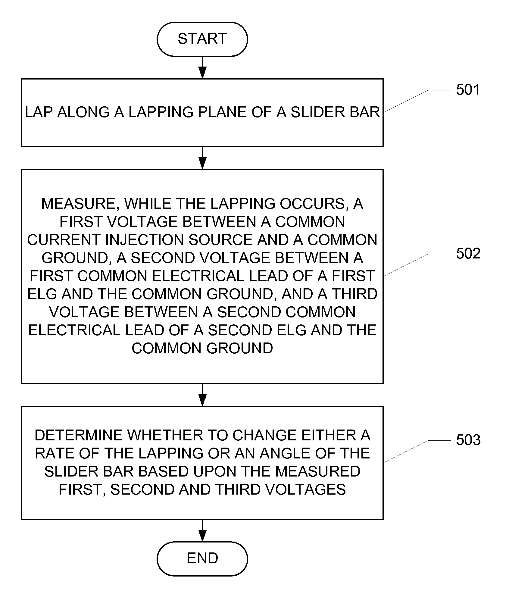
[0014]A machine readable medium carrying one or more sequences of instructions for making a magnetic recording head, wherein execution of the one or more sequences of instructions by one or more processors causes the one or more processors to perform the step of lapping along a lapping plane of a slider bar. The slider bar includes a first differential electronic lapping guide (ELG) disposed in a first layer. The first differential ELG has a first resistive element and a second resistive element between which is disposed a first common electrical lead. The slider bar further includes a second differential ELG disposed in a second layer. The second differential ELG has a third resistive element and a fourth resistive element between which is disposed a second common electrical lead. The first and second differe

Problems solved by technology

While lapping times, lapping pressures, and other lapping parameters could be standardized for particular types of slider bars 52, such a method can be ineffect

Method used


Image

  • Four pad self-calibrating electronic lapping guide
  • Four pad self-calibrating electronic lapping guide
  • Four pad self-calibrating electronic lapping guide

Examples


Embodiment Construction

[0030]In the following detailed description, numerous specific details are set forth to provide a full understanding of the present invention. It will be apparent, however, to one ordinarily skilled in the art that the present invention may be practiced without some of these specific details. In other instances, well-known structures and techniques have not been shown in detail to avoid unnecessarily obscuring the present invention.

[0031]FIG. 2A is a partial cross-sectional view of an electrical lapping guide (ELG) 210 embedded within a reader layer 200 of a slider bar according to one aspect of the subject disclosure. ELG 210 is located near a read sensor 205 with leads 206 and 207. Read sensor 205 may be a magnetoresistive read sensor, and is defined by a height, or stripe height, SH, and a trackwidth, TWS. The relatively close proximity to of ELG 210 to read sensor 205 minimizes fabrication (e.g., dimensional and material property) variations between read sensor 205 and ELG 210. ...


PUM


Abstract

Lapping guides for use in fabrication of a magnetic recording head are provided. The lapping guides comprise a first differential electronic lapping guide (ELG) disposed in a first layer of the magnetic recording head. The first differential ELG has a first resistive element and a second resistive element between which is disposed a first common electrical lead. The lapping guides further comprise a second differential ELG disposed in a second layer of the magnetic recording head. The second differential ELG has a third resistive element and a fourth resistive element between which is disposed a second common electrical lead. The first and second differential ELGs share a common ground and a common current injection source. Remaining lapping distances at the first and second layers of the magnetic recording head are determined by measuring changing voltages across the first, second, third and fourth resistive elements, respectively.

Description

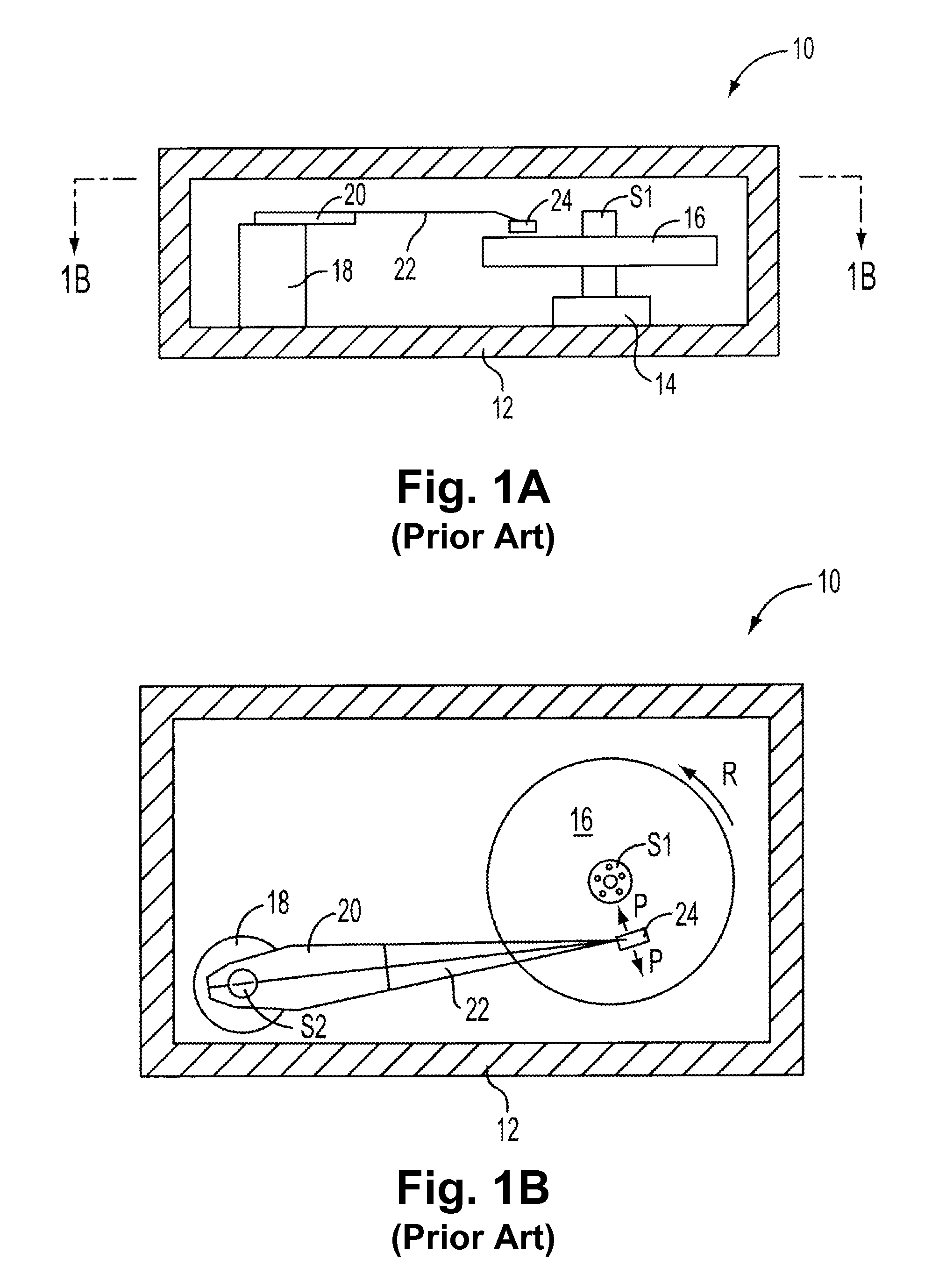
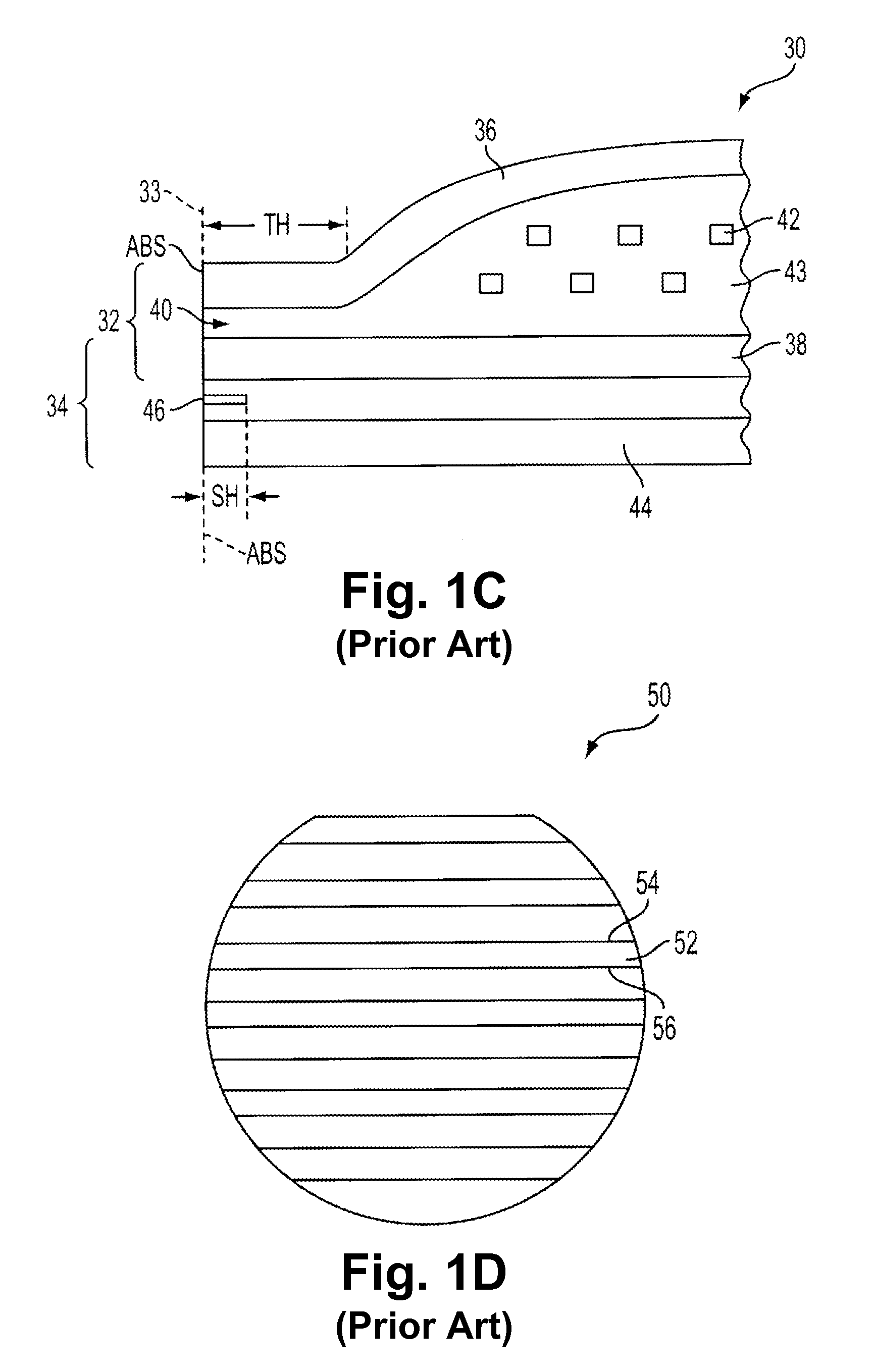
FIELD OF THE INVENTION[0001]The present invention generally relates to electronic lapping guides and, in particular, relates to four pad self-calibrating electronic lapping guides.BACKGROUND OF THE INVENTION[0002]Magnetic disk drives are used to store and retrieve data for digital electronic apparatuses such as computers. In FIGS. 1A and 1B, a magnetic disk drive 10 of the prior art includes a sealed enclosure 12, a disk drive motor 14, a magnetic disk 16, supported for rotation by a spindle S1 of motor 14, an actuator 18 and an arm 20 attached to a spindle S2 of actuator 18. A suspension 22 is coupled at one end to the arm 20, and at its other end to a read / write head or transducer 24. The transducer 24 typically includes an inductive write element with a magnetoresistive read element (shown in FIG. 1C). As the motor 14 rotates the magnetic disk 16, as indicated by the arrow R, an air bearing is formed under the transducer 24 causing it to lift slightly off of the surface of the ma...

Claims


Application Information

Patent Timeline
IPC IPC(8): G06F19/00
CPCG11B5/3166G11B5/3169G11B5/3173
Inventor RUDY, STEVEN C.
Owner WESTERN DIGITAL TECH INC
Why Eureka
Try Eureka