Deadrise-altering adjunct for marine hull bottom

Inactive Publication Date: 2012-05-01
THE UNITED STATES OF AMERICA AS REPRESENTED BY THE SECRETARY OF THE NAVY
View PDF37 Cites 1 Cited by
  • Summary
  • Abstract
  • Description
  • Claims
  • Application Information

AI Technical Summary

Benefits of technology

[0013]The present invention obviates replacement of an existing marine craft with an equally effective but much less costly solution—one that avoids much higher costs associated with acquiring new craft for the environment and threats of a particular locale. A main feature of typical inventive practice is the adjunctive alteration of the deadrise angle of the existing hull. As an example, an 18° deadrise angle may have been originally chosen for a craft's hull to provide a better ride quality for operating in ocean environments, but results in too deep a draft when operating in rocky bottomed or debris-laden rivers. The present invention's add-on structure can reduce the deadrise angle (e.g., a few or several degrees) of the craft's hull bottom, thereby reducing the draft of the craft. For instance, an inventively reduced deadrise angle of 13° may be more suitable than the original 18° deadrise angle for most riverine environments in a given region.
[0014]The shallower draft brought about by the inventive add-on structure not only serves to promote a more suitable draft and a more acceptable ride and maneuvering quality for craft operation in certain river environments, but concomitantly also serves to reduce erosive and damaging contact with the rough terrain of the river bottoms. Furthermore, the inventive add-on structure can represent the second skin/layer of the craft's hull bottom, wherein the original hull bottom represents the first skin/layer. The inventive add-on structure can thus funct

Problems solved by technology

The craft is suitable for its original mission, but is unsuitable or less suitable for its new mission, since the latter imposes requirements that were not taken into consideration in the original design of the craft.
For example, a craft designed to operate at a certain displacement may be subjected to loads much heavier than design loads, due to added equipment or armor.
Accordingly, during its lifecycle a craft may encounter changed circumst

Method used


Image

  • Deadrise-altering adjunct for marine hull bottom
  • Deadrise-altering adjunct for marine hull bottom
  • Deadrise-altering adjunct for marine hull bottom

Examples


Embodiment Construction

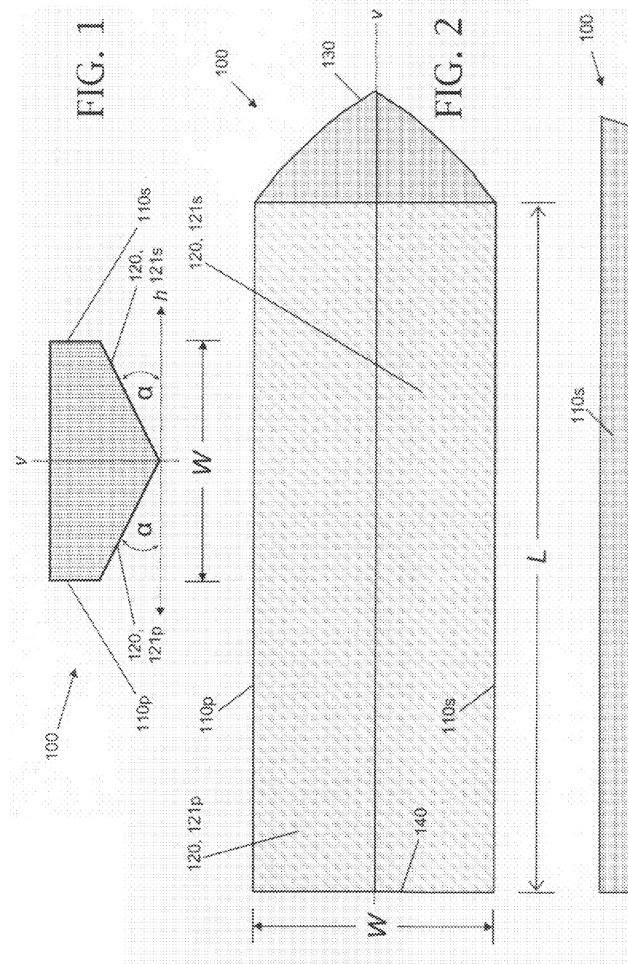
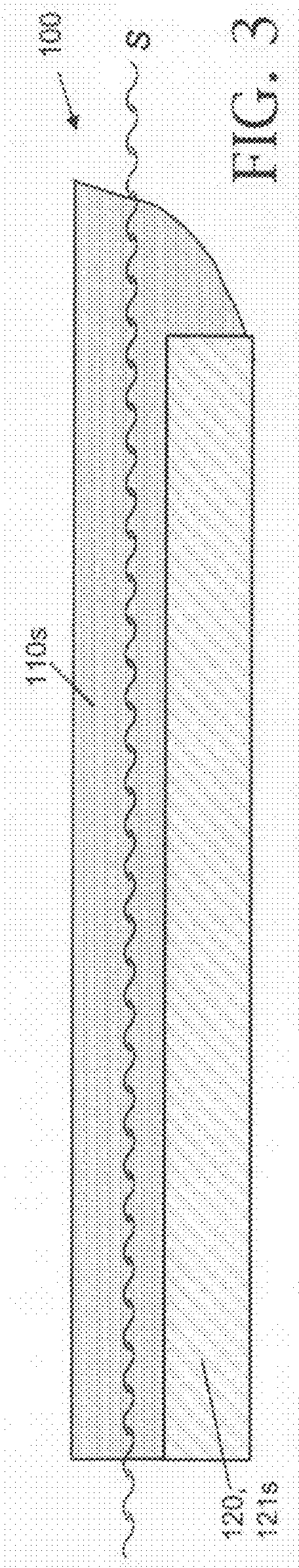
[0033]Referring now to FIG. 1 through FIG. 3, marine vessel hull 100 includes a port (left) side 110p, a starboard (right) side 110s, a hull bottom 120, a bow 130, and a stem 140. Hull bottom 120 is characterized by a hull bottom length L and a hull bottom width W. Hull 100 is symmetrical with respect to a geometric vertical hull-bisector plane v, in which lies hull 100's centerline. Hull 100's waterline s shown in FIG. 3 corresponds to the surface of the water in which hull 100 is afloat.

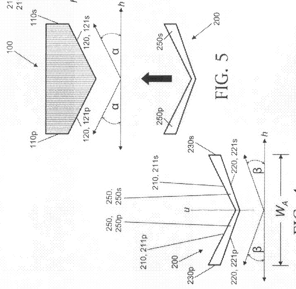
[0034]Hull bottom 120 shown in FIG. 1 is a “V-shaped” hull bottom. A V-shape is illustrated, by way of example, by the equal and opposite upward sloping of hull bottom half-sections 121s and 121p in FIG. 1. Hull bottom 120's two half-sections on opposite sides of geometric vertical bisector plane v—viz., starboard hull bottom half-section 121s and port hull bottom half-section 121p—each describe the same angle α with respect to geometric horizontal plane h.

[0035]The term “V-shape” is conventionally...


PUM


Abstract

As typically embodied, the present invention's add-on device includes two wedge-shaped structural components that are oppositely congruent and symmetrically connected. In profile, the device describes a pair of nearly triangular quadrilateral figures that are enantiomorphs (mirror images) with respect to the linear bisector (mirror line) at which they join. The device's V-angular upper surface defines the same V-angularity (“deadrise”) as does a V-angular hull bottom, the device thus fitting beneath the hull bottom. The device's V-angular lower surface defines a different angularity, which is imparted to the hull bottom when the device is attached thereto. According to typical inventive practice, the device alters the hull bottom's V-angularity by at least 1° and, at least, covers approximately 100% of the hull bottom's widthwise expanse along approximately 50% or more of the hull bottom's lengthwise expanse. The device modifies a marine vessel's hydrodynamics and/or hydrostatics, and may provide armor and/or wear benefits.

Description

BACKGROUND OF THE INVENTION[0001]The present invention relates to marine vessels, more particularly to devices designed to be attached to a marine vessel in order to affect the hydrodynamics and / or hydrostatics of the marine vessel.[0002]It is not uncommon for a vehicle such as a marine vessel to be designed for a particular use and at some point be needed for a different use. This kind of situation is seen, for instance, when a military entity purchases a small craft for one mission, but needs to use that craft for another mission. The craft is suitable for its original mission, but is unsuitable or less suitable for its new mission, since the latter imposes requirements that were not taken into consideration in the original design of the craft.[0003]For example, a craft designed to operate at a certain displacement may be subjected to loads much heavier than design loads, due to added equipment or armor. As another example, a craft may be designed for waters (e.g., in waves at sea...

Claims


Application Information

Patent Timeline
IPC IPC(8): B63B1/00B63B3/08B63B3/10B63B17/00B63B59/02B63G9/02
CPCB63B3/02B63B59/02
Inventor DEMMELMAIER, ALLAN W.JACOBSON, DONALD R.
Owner THE UNITED STATES OF AMERICA AS REPRESENTED BY THE SECRETARY OF THE NAVY
Why Eureka
Try Eureka