Brake dust collecting device for motor vehicles

a technology for motor vehicles and brake dust collectors, which is applied in the direction of cleaning filter means, braking discs, braking systems, etc., can solve the problems of affecting the pressure in the induction tract, changing the air supply into the cylinders of the internal combustion engine, and requiring significant constructive expenditures, etc., to achieve the effect of improving the filtration efficiency

Active Publication Date: 2012-05-01
MANN HUMMEL GMBH
View PDF23 Cites 11 Cited by
  • Summary
  • Abstract
  • Description
  • Claims
  • Application Information

AI Technical Summary

Benefits of technology

[0007]In the brake dust collecting device for motor vehicles according to the invention, the air flow generating device by means of which the air flow is produced that transports the brake dust away from the braking devices is configured in the form of at least one fan blade. This fan blade produces an air flow which is guided in the direction toward the dust collecting unit that is embodied as a filter element. The brake dust that is entrained by the air flow is filtered out by the filter elements; subsequently, the filtered air flow can be released into the atmosphere. The filtration in the filter element enables the best possible cleaning of the air flow. On the one hand, this has the advantage that the environmental loading with particulate matter is significantly reduced and, on the other hand, it is prevented that the brake dust will deposit in the visible area of the wheel rim or on car body parts of the motor vehicle leading to soiling that impairs the aesthetic appearance and that possibly, in certain situations, can cause functional impairments. The air flow is guided in particular from the exterior side of the motor vehicle inwardly and is subjected to filtration in the filter element.
[0012]In case of a rotatable support, the fan blade expediently has the same axis of rotation as the wheel rim. In this embodiment, the fan blade or the fan wheel and the wheel rim can perform a rotation relative to one another which can be used for realization of fluidic effects, for example, for a continuation of the revolution of the fan blade even after decrease of the rotational speed of the wheel rim or upon stopping of the wheel. This is achieved in particular by the inertia of the fan blade or of the fan wheel wherein this effect can be significantly improved or reinforced when on the fan blade or the fan wheel an additional centrifugal mass is provided that significantly increases the moment of inertia and thus also the rotary capability of the fan wheel after braking the wheel. The increased moment of inertia results in that even after termination of the braking process the fan blade or the fan wheel continues to rotate for a certain amount of time and creates an air flow in the direction toward the filter element. In this way, the efficiency of filtration is even more improved to a significant extent.
[0013]Providing an additional centrifugal mass on the fan blade or the fan wheel also has the advantage that in this way with simple measures a fan wheel can be matched to different applications. According to a particularly advantageous further embodiment, the centrifugal mass element is adjustable in the radial direction on the fan blade or the fan wheel, in particular by means of a spring element that secures the centrifugal mass element in a position that is radially retracted adjacent to the axis of rotation. As the vehicle begins to travel, the force of the spring element is still sufficient to secure the centrifugal mass element against the centrifugal force in the position near the axis of rotation. With increasing rotational speed of the wheel the spring forces are overcome and the centrifugal mass element moves radially outwardly along the fan blade or the fan wheel so that the moment of inertia is increased. In this way, the fan wheel can store additional kinetic energy that after braking of the wheel is released and leads to a longer sustained rotation of the fan wheel relative to the wheel rim.
[0015]For improving the filtration efficiency, it can be expedient to design the filter element to be electrostatic. For this purpose, advantageously as a function of momentary state parameters or operating parameters an electrical voltage is supplied to the filter element so that the deposition of electrically loaded dust particles on the filter element is significantly improved. Applying electrical voltage is preferably coupled to the braking process in such a way that the braking process is detected, in particular by actuation of the brake pedal, and in a control unit a signal is generated accordingly by means of which a voltage source is connected to the filter element. When releasing the brake pedal basically also the supply of electrical voltage is canceled, wherein it can be expedient to provide a dead time so that for a certain amount of time even after termination of the braking process the electrical voltage is still supplied to the filter element.
[0016]According to a further advantageous embodiment, between the filter element and the wheel rim a sealing element is provided that is to prevent leakage flows that circumvent the filter element. The sealing element can be connected either fixedly to the filter element or to the wheel rim or with a component that this fixedly coupled to the wheel rim.

Problems solved by technology

This configuration requires a flow connection between the intake manifold of the induction tract of the internal combustion engine and the collecting container for the brake dust; this requires a significant constructive expenditure.
A disadvantage is also to be seen in that by branching off the suction line into the collecting container the pressure in the induction tract is affected so that also the air supply into the cylinders of the internal combustion engine changes.
Moreover, a use in charged internal combustion engines is not possible because of the overpressure produced by the compressor.

Method used


Image

  • Brake dust collecting device for motor vehicles
  • Brake dust collecting device for motor vehicles
  • Brake dust collecting device for motor vehicles

Examples


Embodiment Construction

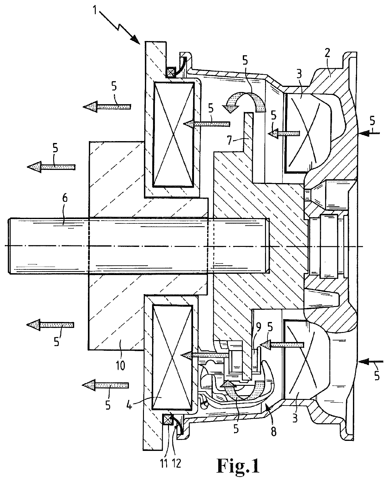
[0033]FIG. 1 shows a brake dust collecting device 1 for brake dust that is produced as abrasion of a motor vehicle disc brake. The brake dust collecting device 1 is received in the interior of a wheel rim 2 and includes fan blades 3 as well as a dust collecting unit in the form of a filter element 4. The fan blades 3 are located on the inner side of the wheel rim 2 that is facing the vehicle and are fixedly connected to the wheel rim. A plurality of such fan blades 3 are distributed about the circumference. The fan blades 3 have a flow-beneficial shape and generate an air flow 5 that is directed from the exterior to the interior and that passes through the openings in the wheel rim 2. The air flow 5 flows across the brake disc 7 against which the brake pads 9 applied by the brake caliper 8 are resting and transports the brake dust to the filter element 4 that is arranged stationarily on the vehicle. The filter element 4 is annularly shaped and is seated on a casing 10 of the wheel b...


PUM


Abstract

A brake dust collecting device for a motor vehicle has a dust collecting unit and an air flow generating device that generates an air flow that flows across brake parts of a motor vehicle wheel brake and that supplies brake dust of the wheel brake to the dust collecting unit. The air flow generating device has a rotatable fan blade and the dust collecting unit is a filter element.

Description

CROSS REFERENCE TO RELATED APPLICATIONS[0001]This application is a continuation application of international application No. PCT / EP2007 / 063460 having an international filing date of 6 Dec. 2007 and designating the United States, the International Application claiming a priority date of 8 Jan. 2007, based on prior filed German patent application No. 20 2007 000 246.7, the entire contents of the aforesaid international application and the aforesaid German patent application being incorporated herein by reference.TECHNICAL FIELD[0002]This disclosure relates to a brake dust collecting device for motor vehicles and, more particularly, to a brake dust collecting device including an air flow generating device for generating an air flow that flows past the brake parts of a motor vehicle wheel brake and carries brake dust of the wheel brake to a dust collecting unit.BACKGROUND OF THE INVENTION[0003]A collecting device for the brake dust that is produced in the motor vehicle wheel brake by ab...

Claims


Application Information

Patent Timeline
Patent Type & Authority Patents(United States)
IPC IPC(8): F16D65/12
CPCB60T3/00B60T17/221F16D65/0031B60T5/00
Inventor JESSBERGER, THOMAS
Owner MANN HUMMEL GMBH
Why Eureka
Try Eureka