Microfluidic apparatuses with nanochannels

a microfluidic and nano-channel technology, applied in the direction of positive displacement liquid engines, laboratory glassware, instruments, etc., can solve the problems of difficult control of channel width and depth, and difficulty in controlling channel size at these submicron dimensions

Active Publication Date: 2012-05-01
AGILENT TECH INC
View PDF9 Cites 1 Cited by
  • Summary
  • Abstract
  • Description
  • Claims
  • Application Information

AI Technical Summary

Problems solved by technology

However, controlling channel sizes at these submicron dimensions is challenging.
For isotropic etching, both channel width and depth can be difficult to control.

Method used


Image

  • Microfluidic apparatuses with nanochannels
  • Microfluidic apparatuses with nanochannels
  • Microfluidic apparatuses with nanochannels

Examples


Embodiment Construction

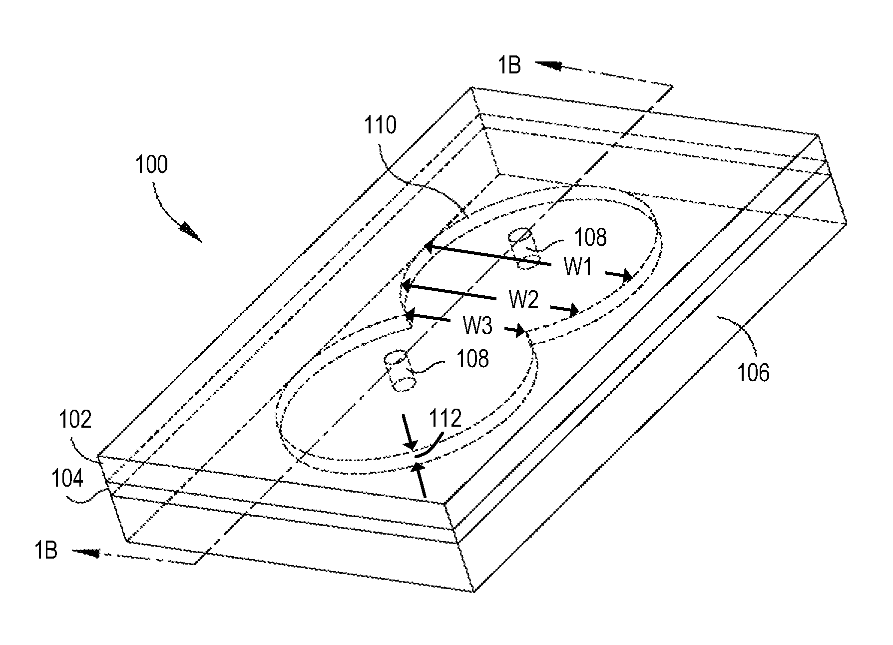
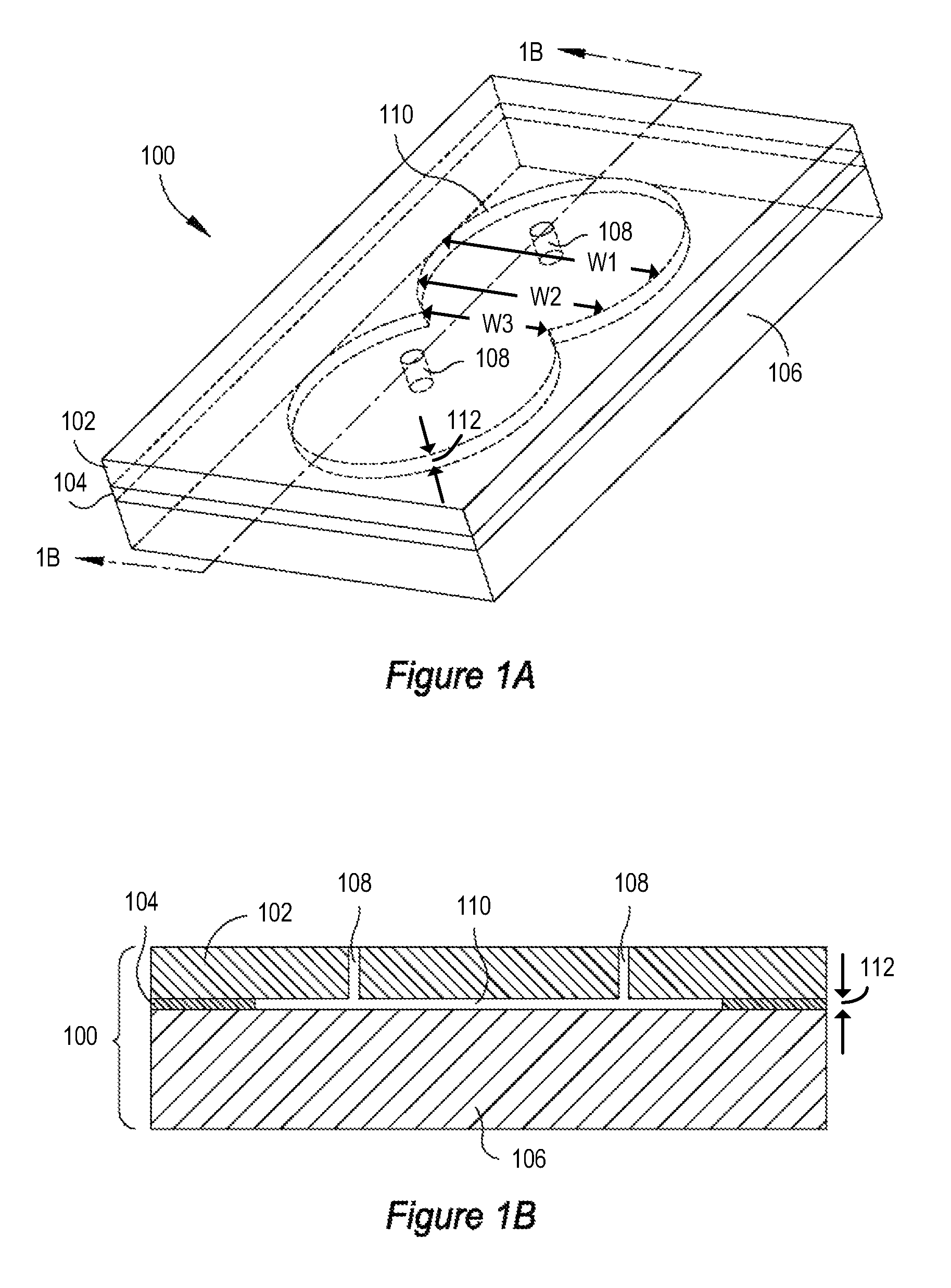
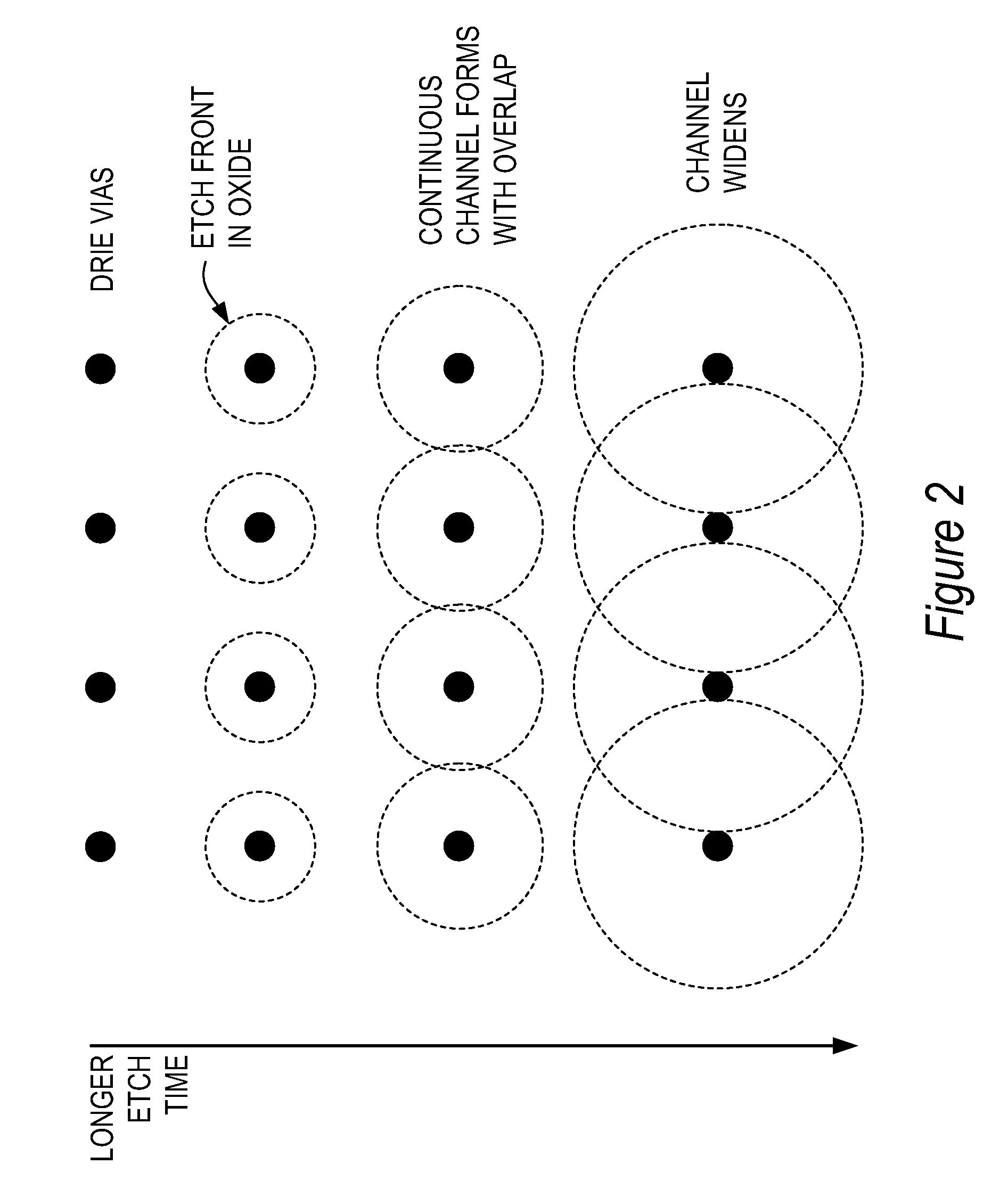
[0011]In some embodiments of the present invention, the buried silicon oxide technology is employed in the fabrication of fluid channels, particularly nanochannels. For example, a fluid channel can be made in a buried silicon oxide layer by etching the buried oxide layer with a method that selectively removes silicon oxide but not silicon. Thus, one dimension of the resulting fluid channel is limited by the thickness of the buried oxide layer. It is possible to manufacture a very thin buried oxide layer with great precision, thus a nanochannel can be fabricated in a controlled manner. Moreover, in addition to silicon and silicon oxide, any pairs of substances with a high etch ratio with respect to each other can be used in the same way. Further provided are the fluid channels, apparatuses, devices and systems comprising the fluid channels, and uses thereof.

[0012]Prior to describing the invention in further detail, the terms used in this application are defined as follows unless othe...


PUM

PropertyMeasurementUnit
heightaaaaaaaaaa
velocityaaaaaaaaaa
velocityaaaaaaaaaa

Abstract

In some embodiments of the present invention, the buried silicon oxide technology is employed in the fabrication of fluid channels, particularly nanochannels. For example, a fluid channel can be made in a buried silicon oxide layer by etching the buried oxide layer with a method that selectively removes silicon oxide but not silicon. Thus, one dimension of the resulting fluid channel is limited by the thickness of the buried oxide layer. It is possible to manufacture a very thin buried oxide layer with great precision, thus a nanochannel can be fabricated in a controlled manner. Moreover, in addition to buried oxide, any pairs of substances with a high etch ratio with respect to each other can be used in the same way. Further provided are the fluid channels, apparatuses, devices and systems comprising the fluid channels, and uses thereof.

Description

BACKGROUND OF THE INVENTION[0001]In the push for better resolution for HPLC (high performance liquid chromatography), the reduction of bead size has been shown to be very effective. At a given pressure, the reduction in bead size will reduce the flow rate, but increase the fluidic impedance of the separation column: for a given pressure, a 2× reduction in average bead diameter will reduce the flow rate by a factor of 4×. While high flow rates are still often desirable, low flow rates are of increasing interest, particularly in the field of proteomics, where sample injection volumes may be quite low and where LC-MS (liquid chromatography-mass spectrometry) flow rates can result in greater mass spectrometer sensitivity.[0002]In systems where nanoflows (flows less than 1 microliter / minute) are required with high applied pressures, the fluidic path will have a high impedance to flow. Narrow channels, such as those with at least one cross-sectional dimension less than one micron (nanocha...

Claims


Application Information

Patent Timeline
Patent Type & Authority Patents(United States)
IPC IPC(8): B01L3/00B01L3/18G01N1/10
CPCB82Y15/00G01N30/6095B01L3/5027B01L2200/12B01L2300/0877Y10T436/2575B01L2300/0887B81C1/00071B82B3/00
Inventor BEERLING, TIMOTHYKRAICZEK, KARSTEN G.BRENNEN, REID A.
Owner AGILENT TECH INC
Why Eureka
Try Eureka