Image sensing device and image sensing system

a sensing device and image technology, applied in the direction of color television details, television system details, television systems, etc., can solve the problem of difficult reduction of total readout period, and achieve the effect of reducing the length of horizontal blanking period

Inactive Publication Date: 2012-05-01
CANON KK
View PDF27 Cites 17 Cited by
  • Summary
  • Abstract
  • Description
  • Claims
  • Application Information

AI Technical Summary

Benefits of technology

[0010]The present invention provides for reducing the length of a horizontal blanking period in a total readout period from a pixel array to an output amplifier.
[0013]According to the present invention, the length of a horizontal blanking period in a total readout period from a pixel array to an output amplifier can be reduced.

Problems solved by technology

As a result, reducing the total readout period becomes difficult.

Method used


Image

  • Image sensing device and image sensing system
  • Image sensing device and image sensing system
  • Image sensing device and image sensing system

Examples


first embodiment

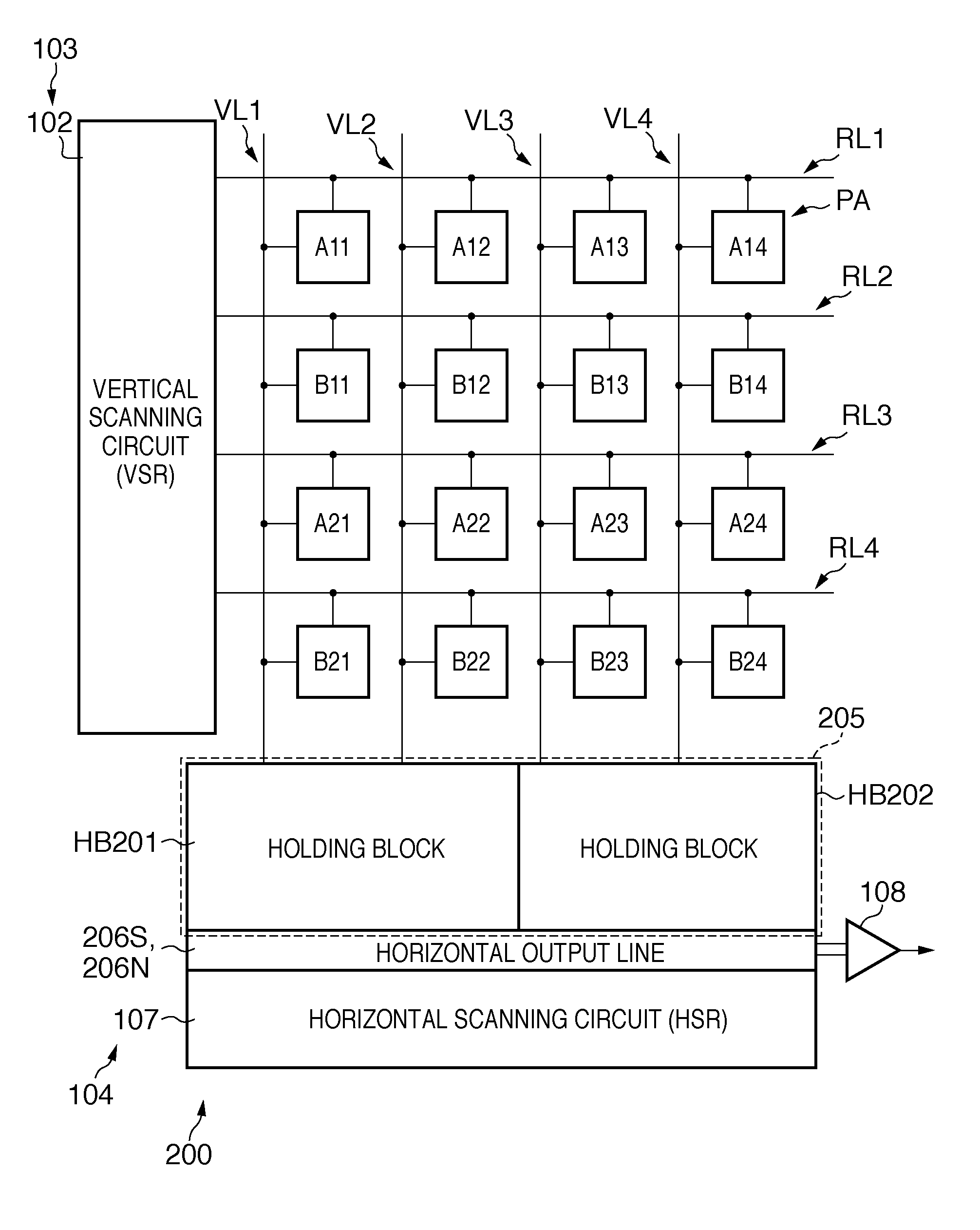
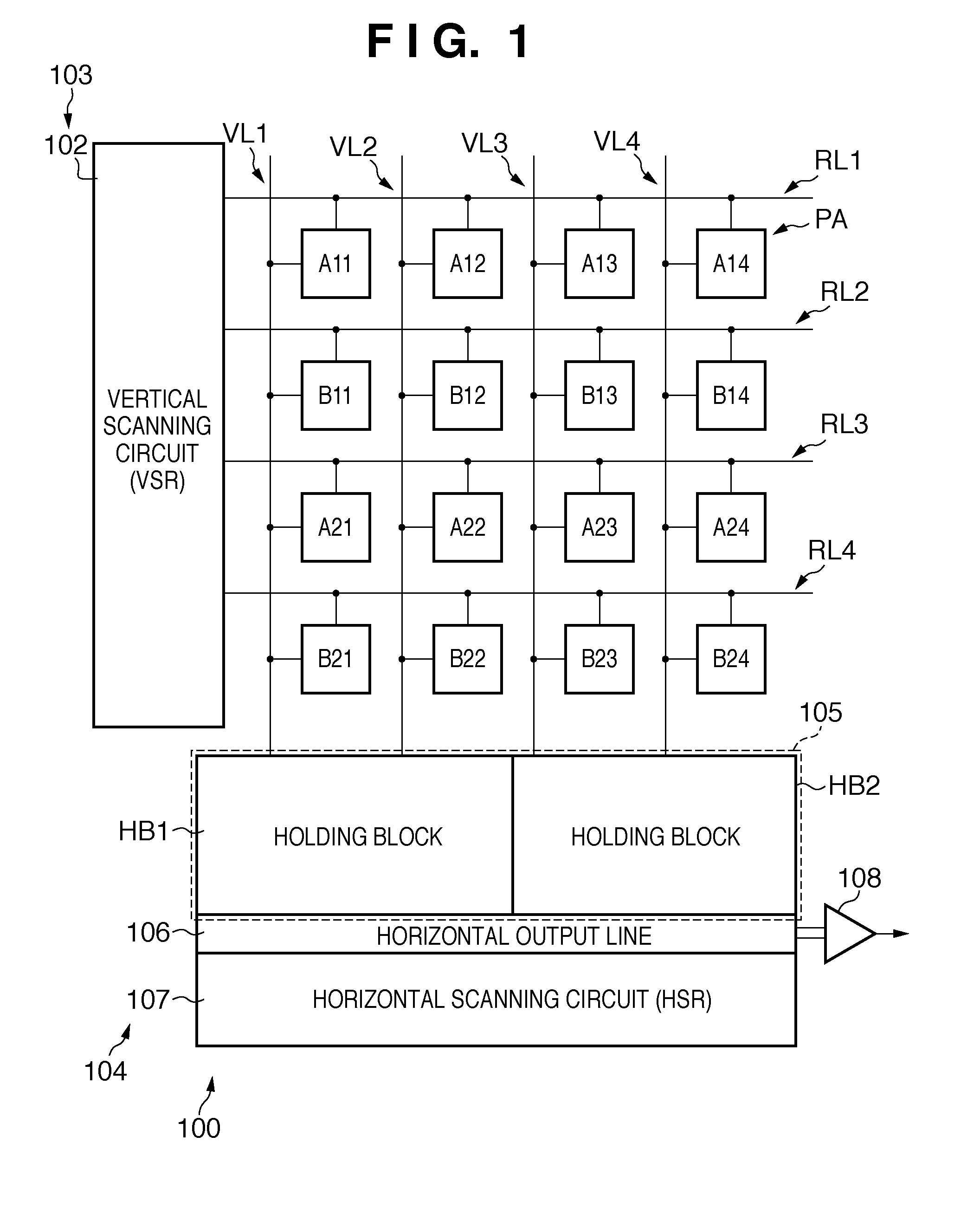
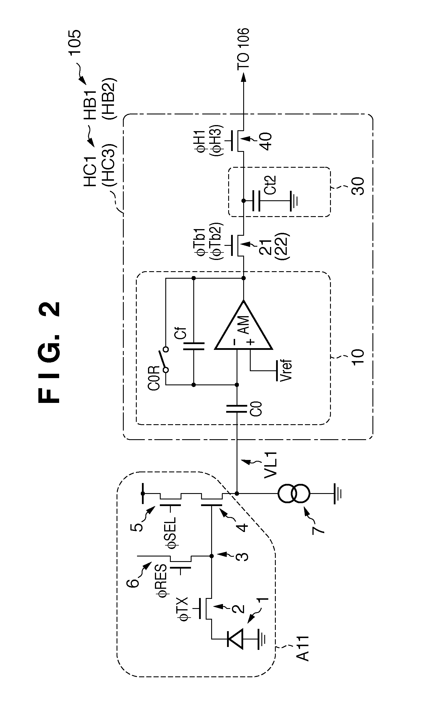
[0041]The configuration of the pixels A11 to B24 in the pixel array PA will be described using FIG. 2. FIG. 2 is an equivalent circuit diagram that simplifies the configuration for one row from a pixel to a horizontal output line in the image sensing device 100 according to the Hereinafter, the configuration of the pixel A11 will be illustratively described, although the configuration of the other pixels is similar.

[0042]The pixel A11, as shown in FIG. 2, includes a photoelectric conversion unit 1, a transfer unit 2, a charge-voltage converter 3, a reset unit 6, an output unit 4, and a selection unit 5.

[0043]The photoelectric conversion unit 1 generates and stores charges according to light. The photoelectric conversion unit 1 is, for example, a photodiode.

[0044]The transfer unit 2 transfers the charges generated by the photoelectric conversion unit 1 to the charge-voltage converter 3. The transfer unit 2 is, for example, a transfer transistor, and transfers the charges generated b...

second embodiment

[0120]FIG. 13 is a timing chart showing the operation of the column signal holding circuits in the holding blocks. Here, the operation of the column signal holding circuit HC301 in the holding block HB301 will be illustratively described. The points that differ from the timing will be mainly discussed.

[0121]At time t44, the vertical scanning circuit 102 supplies an active level control signal φTnb1 to the noise signal transfer switches 323N and 321N. The noise signal transfer switch 323N, by being turned on, thereby transfers the noise signal held in the first noise signal holding unit Ctn1 to the buffer amplifier AMNS. The buffer amplifier AMNS amplifies the transferred noise signal, and transfers the amplified noise signal to the noise signal transfer switch 321N. The noise signal transfer switch 321N, by being turned on, transfers the transferred noise signal to the second noise signal holding unit Ctn2. The second noise signal holding unit Ctn2 holds the noise signal transferre...


PUM


Abstract

An image sensing device comprises a readout unit, an output amplifier, and a horizontal scanning unit, wherein the horizontal scanning unit scans a plurality of column signal holding circuits in a plurality of holding blocks in the readout unit in a direction along a row, in each holding block, a first operation in which the signal held in a first holding unit is transferred to a second holding unit via a transfer switch is performed, and subsequently, a second operation in which the signal held in the second holding unit is transferred to the output amplifier, and a third operation in which a signal output from a pixel is read out to the first holding unit are performed in parallel, and the second operation and the first operation are performed in parallel between different holding blocks in the plurality of holding blocks.

Description

BACKGROUND OF THE INVENTION[0001]1. Field of the Invention[0002]The present invention relates to an image sensing device and an image sensing system.[0003]2. Description of the Related Art[0004]In Japanese Patent Laid-Open No. 2001-45378, it is disclosed that in an solid-state image sensing device, a row selection line connected to the pixels of each row in a pixel array in which a plurality of pixels a11 to b23 are arrayed in a direction along a row and in a direction along a column is scanned by a vertical shift register VSR (see FIG. 1 of Japanese Patent Laid-Open No. 2001-45378). In this solid-state image sensing device, a vertical signal line that is connected to the pixels of a column in the pixel array is connected to a storage unit 1 at one end and a storage unit 2 at the other end. The vertical shift register VSR transfers the signals of the pixels (a11 to a13) of an odd row in the pixel array to the storage unit 1, as shown in FIG. 2 of Japanese Patent Laid-Open No. 2001-4...

Claims


Application Information

Patent Timeline
Patent Type & Authority Patents(United States)
IPC IPC(8): H04N5/335H04N5/374H04N5/376H04N5/378
CPCH04N5/3742H04N25/767
Inventor RYOKI, TATSUYAKOIZUMI, TORUOGURA, MASANORI
Owner CANON KK
Why Eureka
Try Eureka