Detector element matrix for an optical position measuring instrument

Inactive Publication Date: 2012-05-01
DR JOHANNES HEIDENHAIN GMBH
View PDF17 Cites 5 Cited by
  • Summary
  • Abstract
  • Description
  • Claims
  • Application Information

AI Technical Summary

Benefits of technology

[0012]It is therefore an object of the present invention to disclose a detector element array for an optical position measuring instrument which has a high pixel density, is adaptable flexibly to the most various scanning configurations, and does not require major effort and expense for circuitry.
[0015]Thus, as an advantage of the version according to the present invention, in comparison to the prior art, the result is a detector element array of considerably less complexity in terms of circuitry; the number of switches and detector elements as well as memory elements required can be reduced markedly. Moreover, because of the reduced circuit complexity, a higher pixel density is attainable than in arrangements in accordance with the prior art; that is, in the final analysis, substantially increased optical resolution in scanning is obtained. On account of the more-favorable ratio of the available detector element area to the required area of the memory elements and switches, a higher photocurrent yield per unit of detector element area also results. Thus the scanning produces better signal quality for the same total area of the detector element array.

Problems solved by technology

However, the design and adaptation of such detector element arrays to different scanning configurations involves relatively major effort and expense.
The adaptability of the particular detector element arrays to various scanning configurations, however, is possible to only a limited extent.
The provisions proposed in this reference do make even further-improved flexible adaptation of the detector element array to various scanning configurations possible, but because of the many switches and memory elements, it necessitates relatively high effort and expense for circuitry.
Moreover, because of the complicated circuit, the number of available detector elements per unit of surface area decreases; that is, there is only a relatively low resultant pixel density.

Method used


Image

  • Detector element matrix for an optical position measuring instrument
  • Detector element matrix for an optical position measuring instrument
  • Detector element matrix for an optical position measuring instrument

Examples


Embodiment Construction

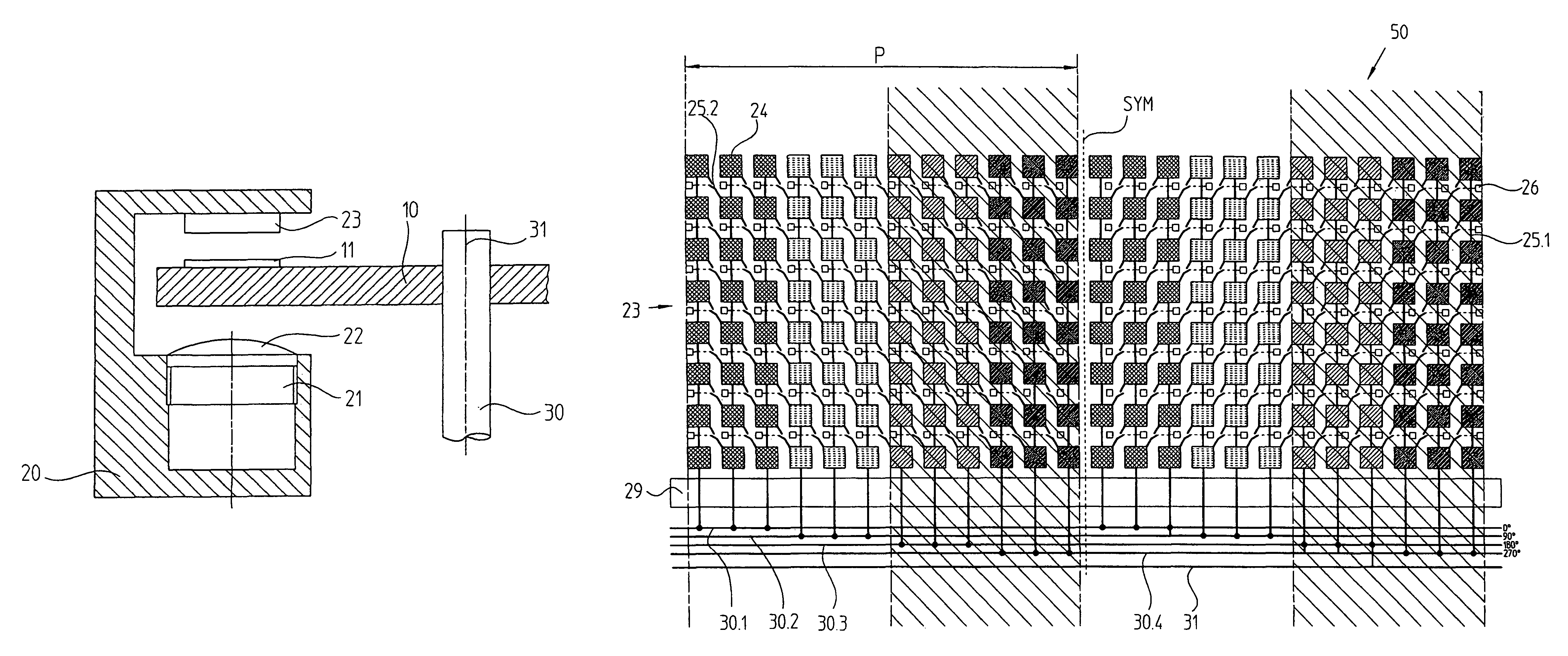
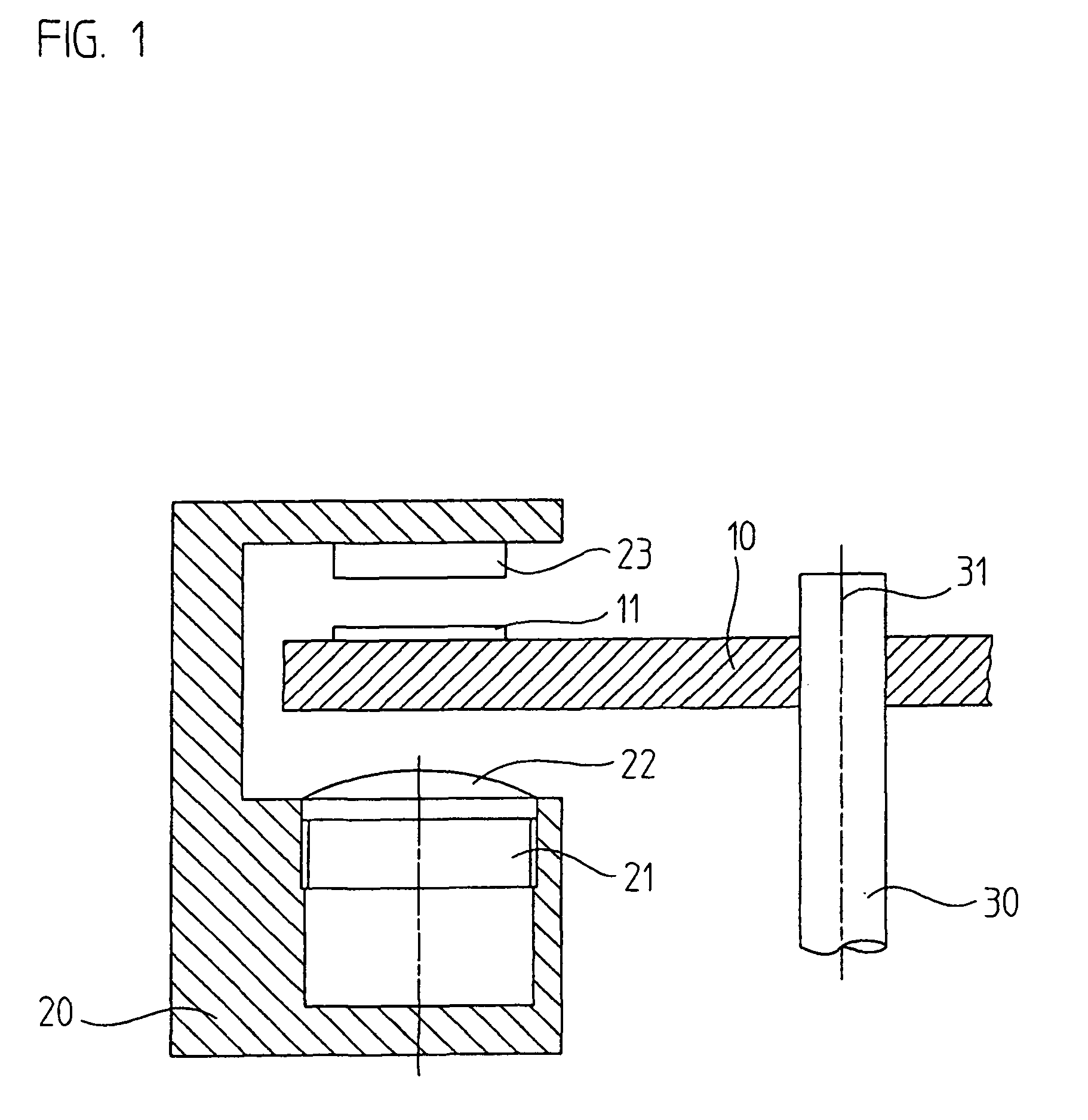
[0049]In FIG. 1, in a highly schematic illustration, a rotational optical position measuring instrument is shown, which is equipped with the detector element array 23 of the present invention. The position measuring instrument serves to generate position information regarding the relative motion of an object, which is not shown in the drawing, rotating about the axis 31. Such an instrument can be employed for instance in machine tools or in electric drive mechanisms, where it furnishes position information about the rotating object for a higher-order control unit.

[0050]The position measuring instrument shown includes, first, a graduated plate 10, on which an incremental graduation 11 is disposed. The graduation 11 includes a track, disposed in a circular ring around the axis 31, with alternating transparent and nontransparent regions that are each embodied rectangularly; the nontransparent regions may be provided with a chromium coating, for instance. The graduated plate 10 is cente...


PUM


Abstract

A detector element array for an optical position measuring instrument, by way of such array a fringe pattern resulting in a detector plane can be converted into electrical scanning signals. The detector element array includes a plurality of light-sensitive detector elements disposed in matrix-like fashion in rows and columns. The plurality of light-sensitive detector elements include a first detector element in a first column of the columns, a second detector element in the first column that is adjacent to the first detector element and a third detector element in a second column of the columns that is adjacent to the first column, wherein the third detector element is diagonally adjacent to the first detector element. The detector element array includes a first switch that selectively directly connects the first detector element with the second detector element and a second switch that selectively directly connects the first detector element with the third detector element. The detector element array includes a memory element associated with the first detector element, wherein memory element information is stored in the memory element that indicates which of the second and third detector elements is connected to the first detector element in an established scanning configuration, wherein no more than the first and second switches are associated with the memory element.

Description

[0001]Applicant claims, under 35 U.S.C. §§120 and 365, the benefit of priority of the filing date of Sep. 27, 2008 of a Patent Cooperation Treaty patent application, copy attached, Ser. No. PCT / EP2008 / 008245, filed on the aforementioned date, the entire contents of which are incorporated herein by reference, wherein Patent Cooperation Treaty patent application Ser. No. PCT / EP2008 / 008245 was not published under PCT Article 21(2) in English.[0002]Applicant claims, under 35 U.S.C. §119, the benefit of priority of the filing date of Oct. 20, 2007 of a German patent application, copy attached, Ser. No. 10 2007 050 253.4, filed on the aforementioned date, the entire contents of each of which are incorporated herein by reference.BACKGROUND OF THE INVENTION[0003]1. Field of the Invention[0004]The present invention relates to a detector element array for an optical position measuring instrument.[0005]2. Description of the Related Art[0006]Known position measuring instruments typically includ...

Claims


Application Information

Patent Timeline
IPC IPC(8): G01B11/02
CPCG01D5/34715
Inventor OBERHAUSER, JOHANN
Owner DR JOHANNES HEIDENHAIN GMBH
Why Eureka
Try Eureka