Anti-expansion joint bridge constructed through detailed survey for bridge

a bridge and detailed survey technology, applied in bridges, bridge structural details, roads, etc., can solve the problems of reducing the driving comfort of expansion joints, affecting the safety of pedestrians, and affecting the safety of expansion joints, so as to prevent running noise and friction

Inactive Publication Date: 2012-05-08
KIM EUN JOO
View PDF18 Cites 32 Cited by
  • Summary
  • Abstract
  • Description
  • Claims
  • Application Information

AI Technical Summary

Benefits of technology

[0025]One aspect of the present invention is to provide an anti-expansion joint bridge which is capable of preventing running noise and friction when vehicles travel over the bridge and is wells suited to a bridge structure which expands and contracts depending on load and temperature variation.
[0026]Another aspect of the present invention is to provide an anti-expansion joint bridge capable of coping with expansion and contraction of a bridge structure and preventing a portion of a pier from being damaged through decentralization of load applied thereto without employing an expansion / contraction groove between piers for absorbing expansion and contraction of the bridge structure.
[0027]A further aspect of the present invention is to provide an anti-expansion joint bridge capable of eliminating a need for frequent replacement of an expansion joint, which is caused by exposure to exposure to the outside and occurrence of resultant damage, thereby reducing financial loses.

Problems solved by technology

However, such an expansion joint has drawbacks of consuming considerable time to construct and complicating a process of paving the bridge with asphalt or concrete.
Further, the expansion joint degrades driving comfort when a vehicle passes over a bridge and is the most likely portion of the bridge to be damaged.
Furthermore, damaged expansion joints are difficult to repair or replace, and during maintenance work, if any, repairmen face considerable danger and traffic congestion may occur.
Here, difficulty in repair or replacement of expansion joints is due to the fact that an anchor bar of the expansion joint is firmly welded to an iron piece embedded in the concrete.
Further, since the expansion joint has substantially the same length as the width of the bridge and has a variety of shapes such as a toothed shape, a slight difference in height from a region near the expansion joint and from the pavement, or unevenness thereof causes vehicles traveling at high speed to be subjected to direct impact, which causes both the extension joint and vehicle tires to be easily damaged and broken.
However, expansion joints as currently constructed are subjected to breakage or damage at the rail or lower support structure thereof due to deterioration and external pressure or shock caused by vehicles travelling thereon.
Such broken or damaged expansion joints must be frequently replaced.
However, the conventional expansion joint structure has a problem in that the presence of the expansion / contraction grooves 5 on the expansion joint 10 rattles when vehicles travel thereover, thereby degrading driving comfort.
That is, the conventional expansion joint structure has an uneven and irregular upper surface, thereby significantly deteriorating driving comfort.
That is, when a vehicle passes over the expansion / contraction grooves 5, rattling shock occurs and is transferred to the end of the non-contracting concrete slabs 3, 3′, which increases the likelihood of breakage.
If defects such as breakage, failure, or the like occur on such an expansion joint, water leakage occurs and a bridge seat structure supporting the floor slab of the bridge becomes rusty, resulting in fatal damage.
In this case, rust stains on a capping stone on a pier detract from the appearance of the bridge and cause concrete structures to be subjected to severe fracture and breakage.
Particularly, if a portion of the non-contracting concrete slabs 3, 3′ is damaged, assembly of the expansion joint 10 becomes defective, thereby causing bridge failure and exposing the pier to a danger of collapse.
Further, since the expansion joint 10 exposed through the expansion / contraction grooves 5 is likely to suffer from breakage owing to load applied by vehicles travelling thereover and internal stress caused by expansion and contraction of the non-contracting concrete slabs 3, 3′, the damaged expansion joint 10 must be frequently replaced, thereby causing considerable costs associated with replacement of the expansion joint 10.

Method used


Image

  • Anti-expansion joint bridge constructed through detailed survey for bridge
  • Anti-expansion joint bridge constructed through detailed survey for bridge
  • Anti-expansion joint bridge constructed through detailed survey for bridge

Examples


Embodiment Construction

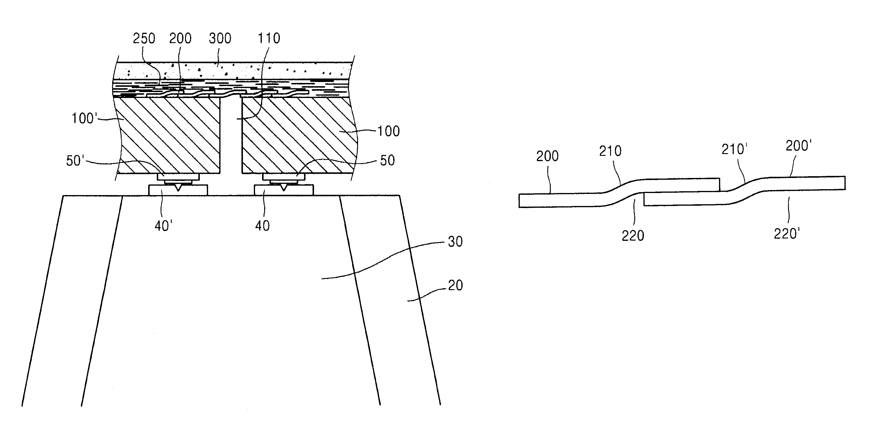
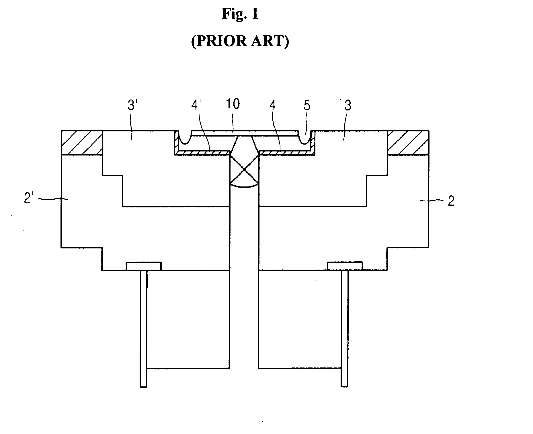
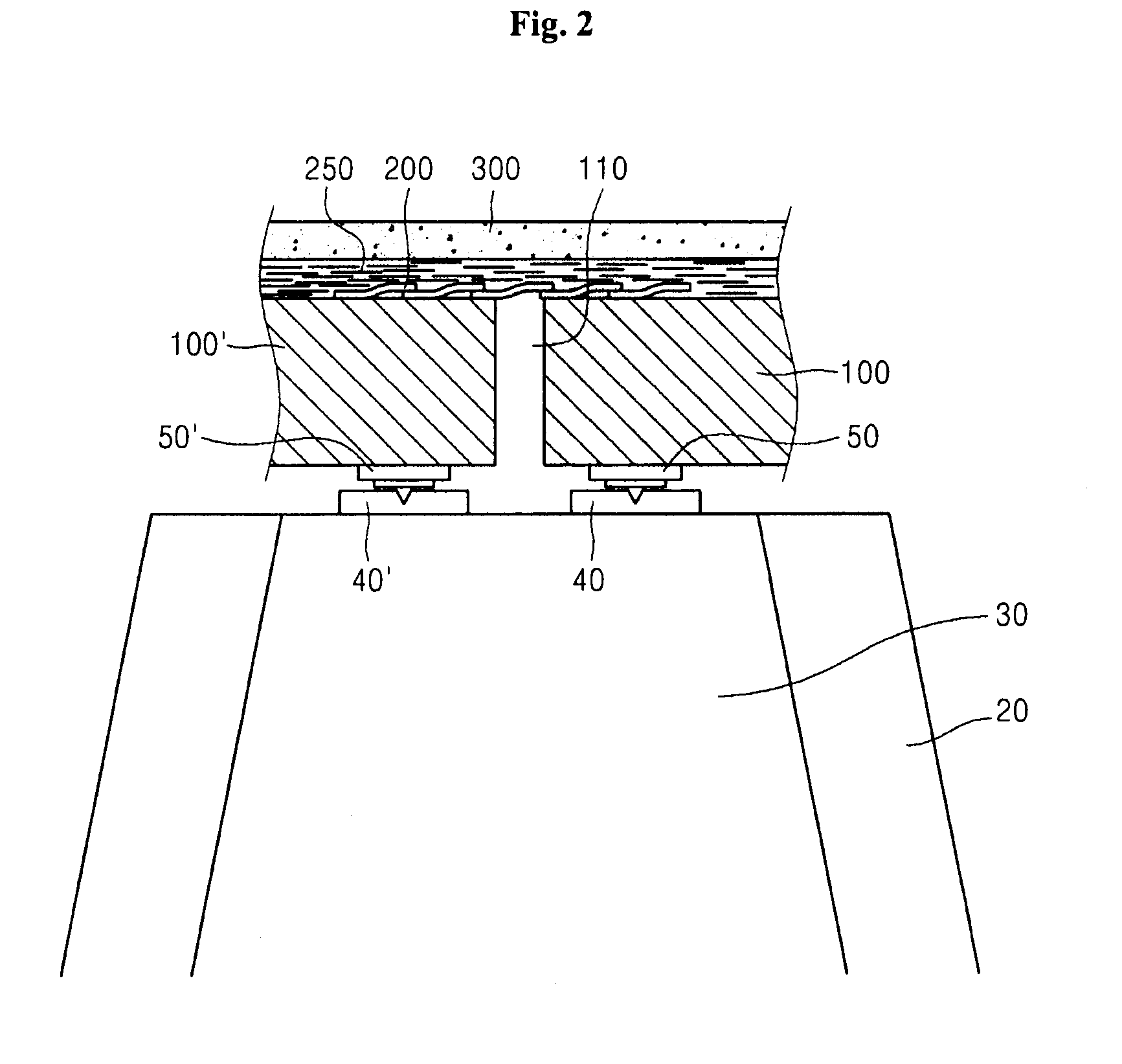
[0047]Exemplary embodiments of the invention will now be described in detail with reference to the accompanying drawings. The following embodiments are given by way of illustration to provide a thorough understanding of the invention to those skilled in the art. Hence, it should be understood that the embodiments of the invention are different from each other but are not exclusive with respect to each other. For example, certain shapes, configurations and features disclosed herein may be realized by other embodiments without departing from the spirit and scope of the invention. Further, it should be understood that positions and arrangement of individual components in each of the embodiments may be changed without departing from the spirit and scope of the invention. Therefore, the following detailed description should not be construed as limiting the claims to the specific embodiments, but should be construed to include all possible embodiments along with the full scope of equivale...


PUM


Abstract

Disclosed herein is an anti-expansion joint bridge which eliminates an expansion joint structure from an upper structure thereof, and includes a plurality of slidable steel plates to cover a space between girders or floor slabs expanding and contracting on piers and asphalt concrete pavement on the steel plates, so that expansion and contraction of the girders occurring on the piers is prevented from affecting the pavement, thereby ensuring smooth travel of vehicles thereon. The anti-expansion joint bridge includes a pair of expandable / contractible girders separated from each other while constituting an upper structure of the bridge, a plurality of sliding plates overlapping each other on the girders while covering a gap between the girders, and an ascon part covering the pair of girders together with the sliding plates.

Description

BACKGROUND[0001]1. Technical Field[0002]The present invention relate to an anti-expansion joint bridge and, more particularly, to an anti-expansion joint bridge which eliminates an expansion joint structure from an upper structure thereof, and includes a plurality of slidable steel plates to cover a space between girders or floor slabs expanding and contracting on piers and asphalt concrete pavement on the steel plates, so that expansion and contraction of the girders occurring on the piers is prevented from affecting the pavement, thereby ensuring smooth travel of vehicles thereon.[0003]2. Description of the Related Art[0004]It is estimated that the first bridges were made by humans in prehistoric times. These bridges probably took the form of a tree trunk, a wisteria vine, or the like fallen across a river or a valley and were developed from there. It is assumed that in early bridges, cut tree trunks were transported and installed across valleys or rivers. If a single tree trunk w...

Claims


Application Information

Patent Timeline
Patent Type & Authority Patents(United States)
IPC IPC(8): E01D19/06
CPCE01D19/06E01C11/02E01D19/067
Inventor KIM, EUN-JOO
Owner KIM EUN JOO
Why Eureka
Try Eureka