Method, system and apparatus for liquid injection into a gas system

a technology of emission liquid and gas stream, which is applied in the direction of lighting and heating apparatus, separation processes, arsenic compounds, etc., can solve the problems of reduced scr catalyst performance, reduced ammonia storage, and large residual time of reductant evaporation, so as to increase the travel time and the effect of increasing the temperatur

Active Publication Date: 2012-05-08
INT ENGINE INTPROP CO LLC
View PDF9 Cites 14 Cited by
  • Summary
  • Abstract
  • Description
  • Claims
  • Application Information

AI Technical Summary

Benefits of technology

[0006]A method for injection of a liquid reductant into an exhaust gas and for evaporating and decomposing the liquid reductant at an elevated temperature includes providing an exhaust pipe having an interior surface and disposing the exhaust pipe in fluid communication with and upstream of a catalyst. The method also includes the steps of disposing an internal cone within the exhaust pipe generally parallel to the exhaust pipe, mounting an injector to the exterior of the exhaust pipe in fluid communication with the internal cone, injecting the liquid reductant into the internal cone, and directing the exhaust gas in a passage between the interior surface of the exhaust pipe and the internal cone. The exhaust gas is also directed within the internal cone. The flow of exhaust gas has an elevated temperature compared to an ambient. A further step includes creating a drag force on the injected liquid reductant to increase the travel time of the injected liquid reductant from the injector to the catalyst.

Problems solved by technology

Nitrogen oxides can be reduced by ammonia, however ammonia is difficult to store.
If the evaporation and the decomposition are not complete, the SCR catalyst performance is reduced due to insufficient availability of reductant.
However, with larger engines having exhaust gas flow of 170 m3 / hour to 1130 m3 / hour, the residual time of the reductant evaporation is still larger than the travel time to the catalyst.

Method used


Image

  • Method, system and apparatus for liquid injection into a gas system
  • Method, system and apparatus for liquid injection into a gas system
  • Method, system and apparatus for liquid injection into a gas system

Examples


Embodiment Construction

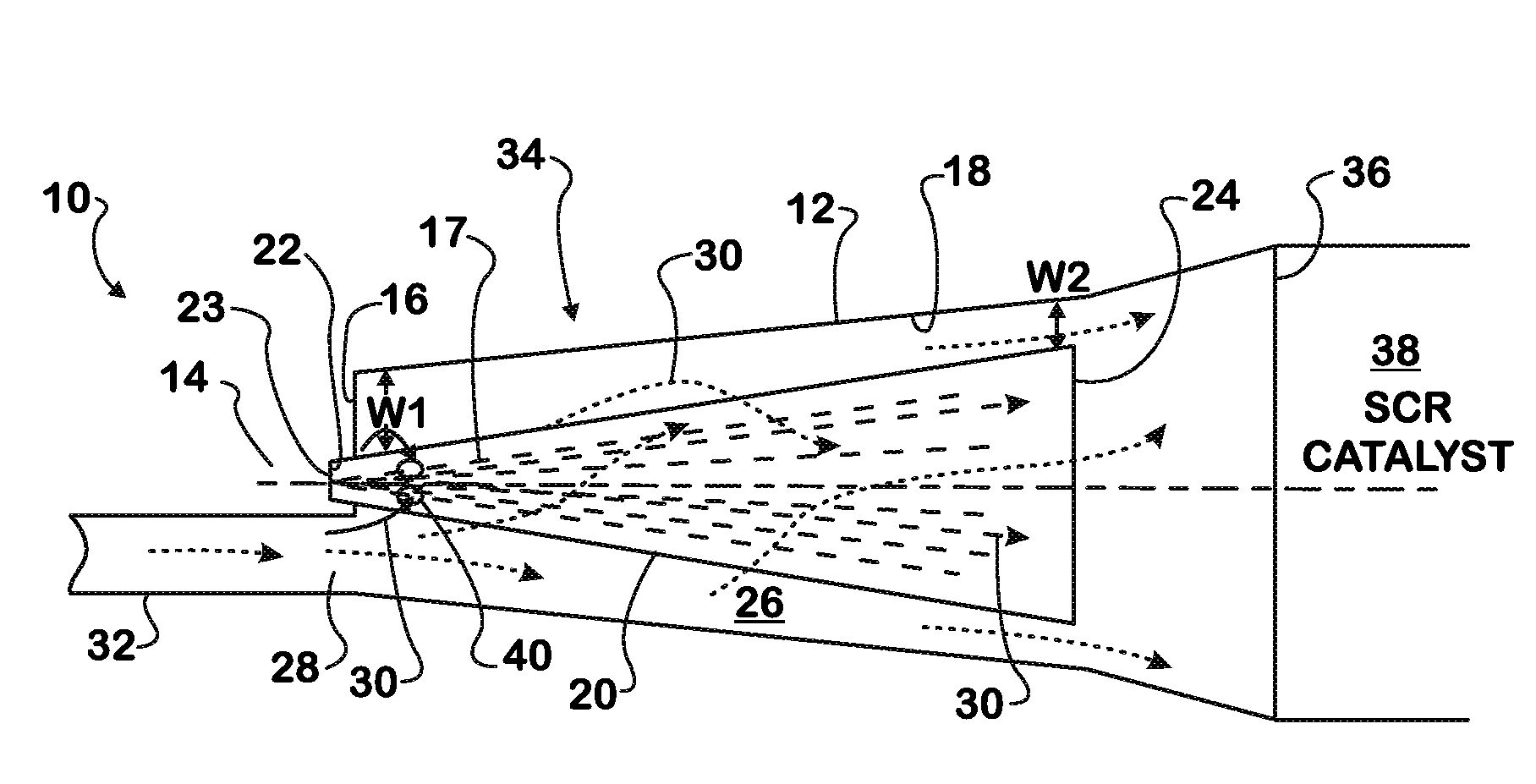
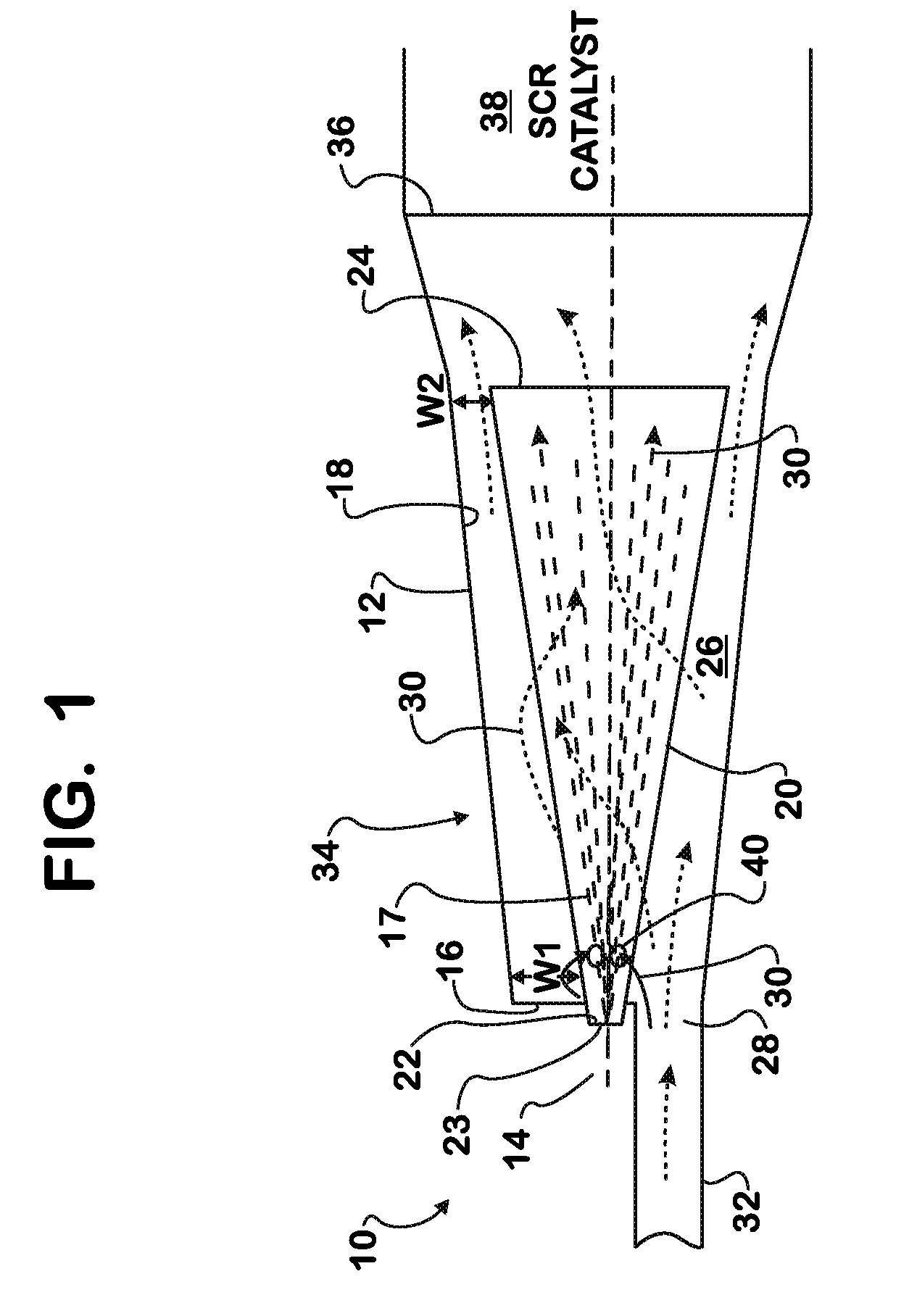
[0009]While the following description will describe one application of the present and method, system and apparatus, it should be appreciated that the present method, system and apparatus is applicable to any liquid reductant into any gas stream. The following will describe the present method, system and apparatus with respect to injecting urea, a liquid reductant, into the gas stream of an SCR system. When an engine combusts diesel, nitrogen oxides form in the flame, and are released with the exhaust gas. Nitrogen oxides, Nox, are a pollutant that are reduced in SCR systems by ammonia, NH3, resulting in the emission of less harmful nitrogen, N2, water, H2O, and carbon dioxide, C02.

[0010]Ammonia is formed when urea decomposes as it is sprayed into a hot exhaust gas mixture in the exhaust pipe. The urea SCR systems rely on injection of 32.5% aqueous urea solution into the exhaust line of a vehicle upstream of an SCR catalyst, where the temperature of the exhaust gases is preferably i...


PUM

PropertyMeasurementUnit
temperatureaaaaaaaaaa

Abstract

A method for injection reductant into an exhaust gas and for evaporating and decomposing the reductant at an elevated temperature includes providing an exhaust pipe having an interior surface and disposing the pipe in fluid communication with and upstream of a catalyst. The method includes the steps of disposing an internal cone within the pipe generally parallel to the pipe, mounting an injector to the exterior of the pipe in fluid communication with the cone, injecting the reductant into the cone, and directing the exhaust gas in a passage between the interior surface of the pipe and the cone. The exhaust gas is directed within the cone. The flow of exhaust gas has an elevated temperature compared to an ambient. A further step includes creating a drag force on the injected reductant to increase travel time of the injected reductant from the injector to the catalyst.

Description

FIELD OF THE INVENTION[0001]The present invention relates generally to a method, system and apparatus for injecting an emission liquid reductant into a gas stream, and more particularly, to a method, system and apparatus for injecting an emission reductant, such as urea, into a gas stream of an aftertreatment system, such as an SCR system.BACKGROUND OF THE INVENTION[0002]Diesel engine combustion results in the formation of nitrogen oxides, (NOx), in the exhaust gas. Typically, urea selective catalytic reduction systems (urea SCR systems) are used to reduce oxides of Nitrogen (NOx) from engines. Nitrogen oxides can be reduced by ammonia, however ammonia is difficult to store. For that reason, urea SCR systems rely on injection of 32.5% aqueous urea solution, which is injected into the exhaust line of a vehicle upstream of an SCR catalyst. In the SCR catalyst, the NOx is reduced by the ammonia, and the emission from the catalyst is N2, H2O and C02.[0003]For efficient performance, the ...

Claims


Application Information

Patent Timeline
Patent Type & Authority Patents(United States)
IPC IPC(8): B01D53/34B01D53/90B01D53/94F01N3/10
CPCF01N3/2066F01N2610/02F01N2610/102F01N2610/14Y02T10/24Y02A50/20Y02T10/12
Inventor MAKARTCHOUK, ANDREIO'CONNOR, JUSTINGRAVANTE, STEVE P.AMIN, EMAD M.SMITH, S. SCOTT
Owner INT ENGINE INTPROP CO LLC
Why Eureka
Try Eureka