
Remote network management system

a network management and remote network technology, applied in the field of remote network management system, can solve the problems of reducing the required bandwidth, reducing the communication time, and most forms of video compression known in the art require complicated calculations, and achieve the effect of convenient installation and operation and readily accessible communication ports

Active Publication Date: 2012-05-08
RIIP
View PDF53 Cites 28 Cited by
  • Summary
  • Abstract
  • Description
  • Claims
  • Application Information

AI Technical Summary

Benefits of technology

"The present invention is a remote network management system that allows users to access, operate, and control networking equipment, servers, and computers at a remote location. The system is connected to a central remote management unit (RMU) through a network, and the RMU is connected to the Internet or a local area network (LAN) through Ethernet or modem. The RMU has a port for each piece of equipment, and it allows users to control the power supply to each piece of equipment using a keyboard, video monitor, and cursor control device attached to their workstation. The RMU can communicate with the user workstation through a TCP / IP network. The system uses a lossless compression algorithm to compress and transmit video signals, and the decompression device reconstructs full frames of video and updates its cache with new video data. The system also allows users to display video signals on their workstation monitors. The invention reduces cabling costs and allows for easy transmission of video signals to any user workstation with Internet capabilities."

Problems solved by technology

Reducing the amount of digital data transmitted over the communication medium decreases communication time and decreases the required bandwidth.
Most forms of video compression known in the art require complicated calculations.
Since these algorithms are calculation intensive, they either require expensive hardware or extended transmission times that allow sufficient time for slower hardware to complete the calculations.
In addition to complexity, many existing video compression techniques are lossy (i.e., they do not transmit all of the video signal information in order to reduce the required bandwidth).
Typically, such lossy techniques either reduce the detail of a video image or reduce the number of colors utilized.
Although reducing the number of colors could be part of an adequate compression solution for some computer management systems applications, in many other applications, such a result defeats the intended purposes of the computer management system.
The overlaid video image produced by the on-screen processor, namely a Motorola MC141543 on-screen processor, is limited to the size and quantity of colors and characters that are available with the single on-screen processor.
In other words, the Beasley system is designed to produce an overlaid video that is sized for a standard size computer monitor (i.e., not a wall-size or multiple monitor type video display) and is limited to the quantity of colors and characters provided by the single on-screen processor.

Method used


Image

  • Remote network management system
  • Remote network management system
  • Remote network management system

Examples


Embodiment Construction

[0061]As required, a detailed illustrative embodiment of the present invention is disclosed herein. However, techniques, systems and operating structures in accordance with the present invention may be embodied in a wide variety of forms and modes, some of which may be quite different from those in the disclosed embodiment. Consequently, the specific structural and functional details disclosed herein are merely representative, yet in that regard, they are deemed to afford the best embodiment for purposes of disclosure and to provide a basis for the claims herein which define the scope of the present invention. The following presents a detailed description of the preferred embodiment (as well as some alternative embodiments) of the present invention.

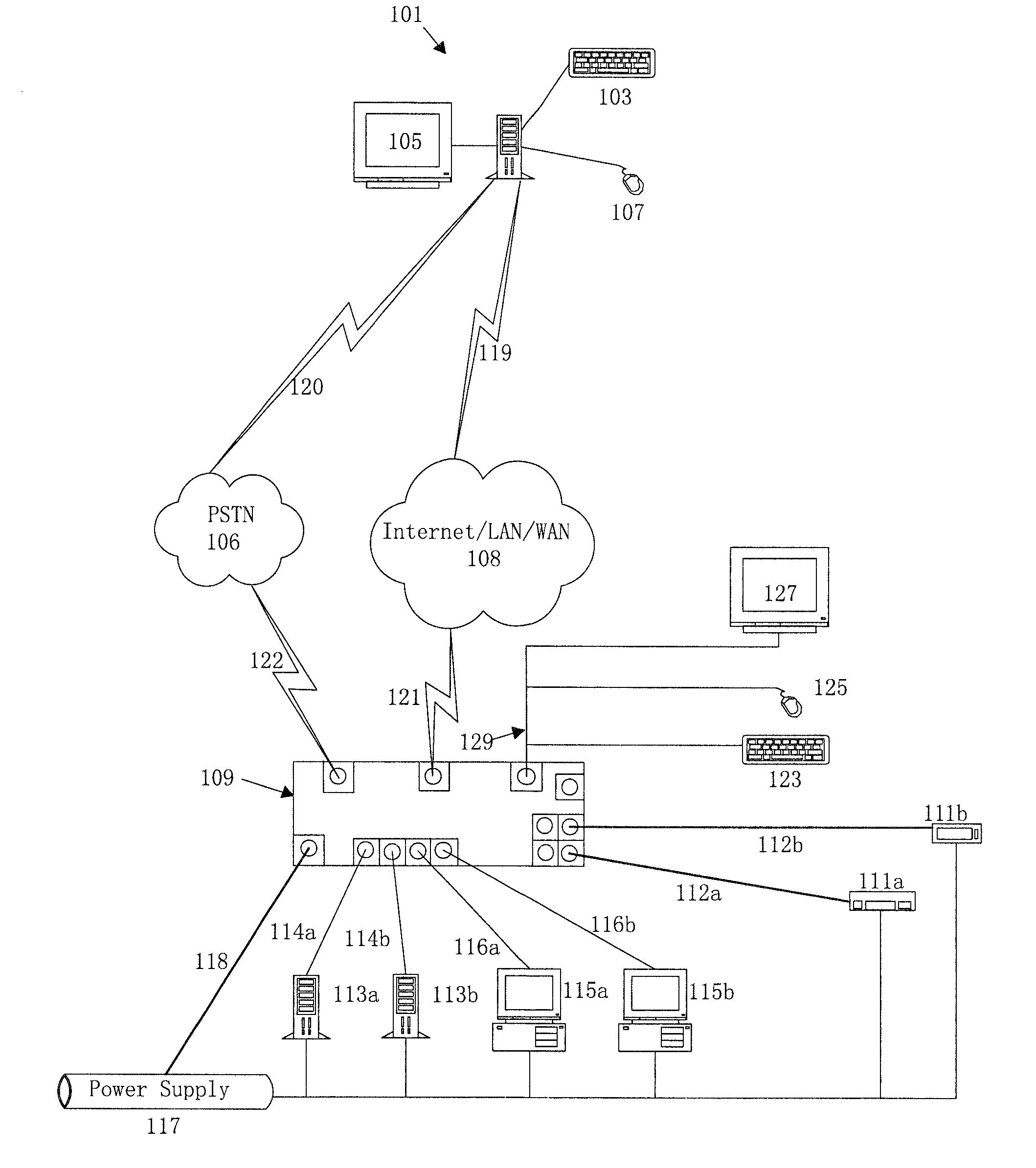
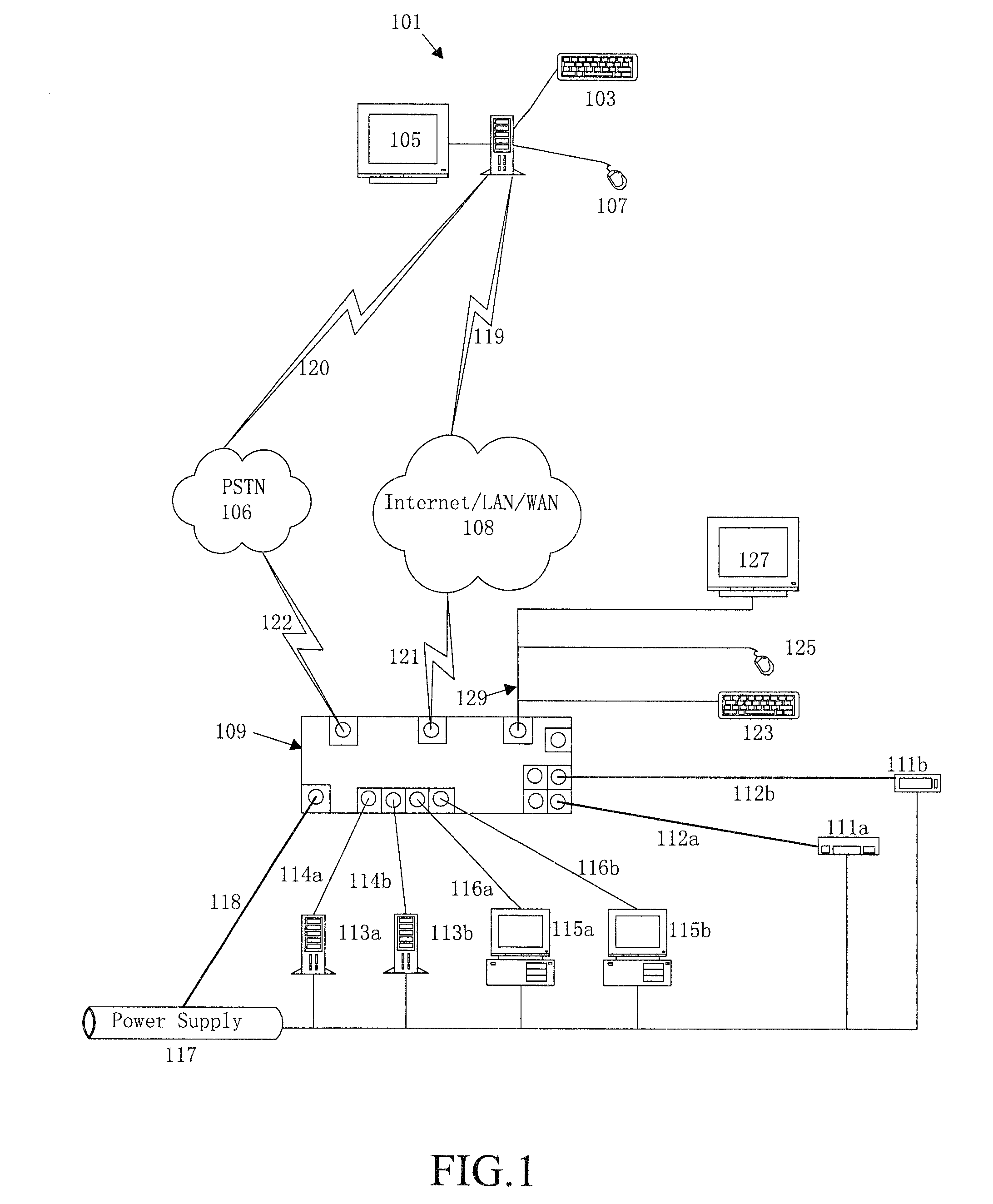
[0062]Referring first to FIG. 1, depicted is the architecture of the preferred embodiment of a remote network management system in accordance with the present invention. Specifically, a remote network management system is shown comprising...


PUM


Abstract

Disclosed is a remote network management system for coupling a series of remote domain servers, file / print servers, headless servers, network appliances, serial IT equipment, switches, routers, firewalls, security interfaces, application servers, load balancers, and environmental controls to one or more user workstations allowing for selective access of the remote devices. The remote devices are all connected to a remote management unit which interfaces each user workstation to the remote devices. The power supply of each remote device is similarly connected to the remote management unit through a controllable power supply. An option menu containing a list of all of the remote devices allows a user to select and operate any of the remote devices from the workstation. The option menu is also utilized to selectively control the power to the remote devices, servers, and computers.

Description

FIELD OF THE INVENTION[0001]The present invention relates generally to a remote network management system for remotely controlling network and computer equipment from one or more local user workstations through a remote control device. Specifically, a keyboard, video monitor, and cursor control device attached to a user workstation are utilized to remotely control domain servers, file / print servers, headless servers, network appliances, serial IT equipment, switches, routers, firewalls, security interfaces, application servers, load balancers, and environmental controls as their associated power supplies are connected to a remote control device.BACKGROUND OF THE INVENTION[0002]In many situations, it is desirable to manage networking equipment, servers, and computers located at a location remote from the system administrator. If the distance is great enough, the Internet is commonly utilized to control computers from a remote location. For example, a software program such as pcAnywhe...

Claims


Application Information

Patent Timeline
Patent Type & Authority Patents(United States)
IPC IPC(8): G06F15/173G06FG06F21/31G06F21/41H04L12/24
CPCG06F3/14H04L67/125G09G2370/24H04L41/0253H04N7/18
Inventor YANG, ALLENLIAW, YEETI, DENNIS
Owner RIIP
Learn More