DMA controller

a controller and controller technology, applied in the field of dma controllers, to achieve the effect of reducing cpu load, high switching speed, and improving system performan

Inactive Publication Date: 2012-05-08
RENESAS ELECTRONICS CORP
View PDF12 Cites 7 Cited by
  • Summary
  • Abstract
  • Description
  • Claims
  • Application Information

AI Technical Summary

Benefits of technology

[0018]The effects obtained by typical aspects of the present invention disclosed in the present application will be briefly described below.
[0019]According to the DMA controller of the present invention, with effectively using a memory bus being a small-scale circuit and having a high switching speed, it becomes possible to perform a DMA transfer by the DMA controller periodically confirming state of the register of the existing peripheral device and a memory independently without having a help of a CPU. Therefore, without embracing the cost of adding a special change to the existing peripheral device, the system performance can be improved with flexibly handling jitter in an operation cycle of the peripheral device and reducing CPU load.BRIEF DESCRIPTIONS OF THE DRAWINGS
[0020]FIG. 1 is a function block diagram illustrating a configuration of a computer system mounting a DMAC according to a first embodiment of the present invention;
[0021]FIG. 2 is a diagram illustrating a configuration of registers in the DMAC according to the first embodiment of the present invention;
[0022]FIG. 3 is a flow chart illustrating a flow of a peripheral device read procedure, a state comparison procedure, and a counter update procedure in the DMAC according to the first embodiment of the present invention;
[0023]FIG. 4 is a flow chart illustrating a flow of a peripheral device read procedure, a state comparison procedure, and a counter update procedure in the DMAC according to the first embodiment of the present invention;

Problems solved by technology

However, if jitter exists in the operation cycle of the peripheral devices, it has been unable to employ the method such as that of Patent Document 1, and it has been required to employ interrupt or the polling method as described above.Patent Document 1: Japanese Patent Application Laid-Open Publication No.

Method used


Image

  • DMA controller
  • DMA controller
  • DMA controller

Examples


first embodiment

[0045]A DMA controller with a peripheral device state confirmation function (hereinafter, called “DMAC”) of a first embodiment of the present invention will be described with reference to FIGS. 1 and 2.

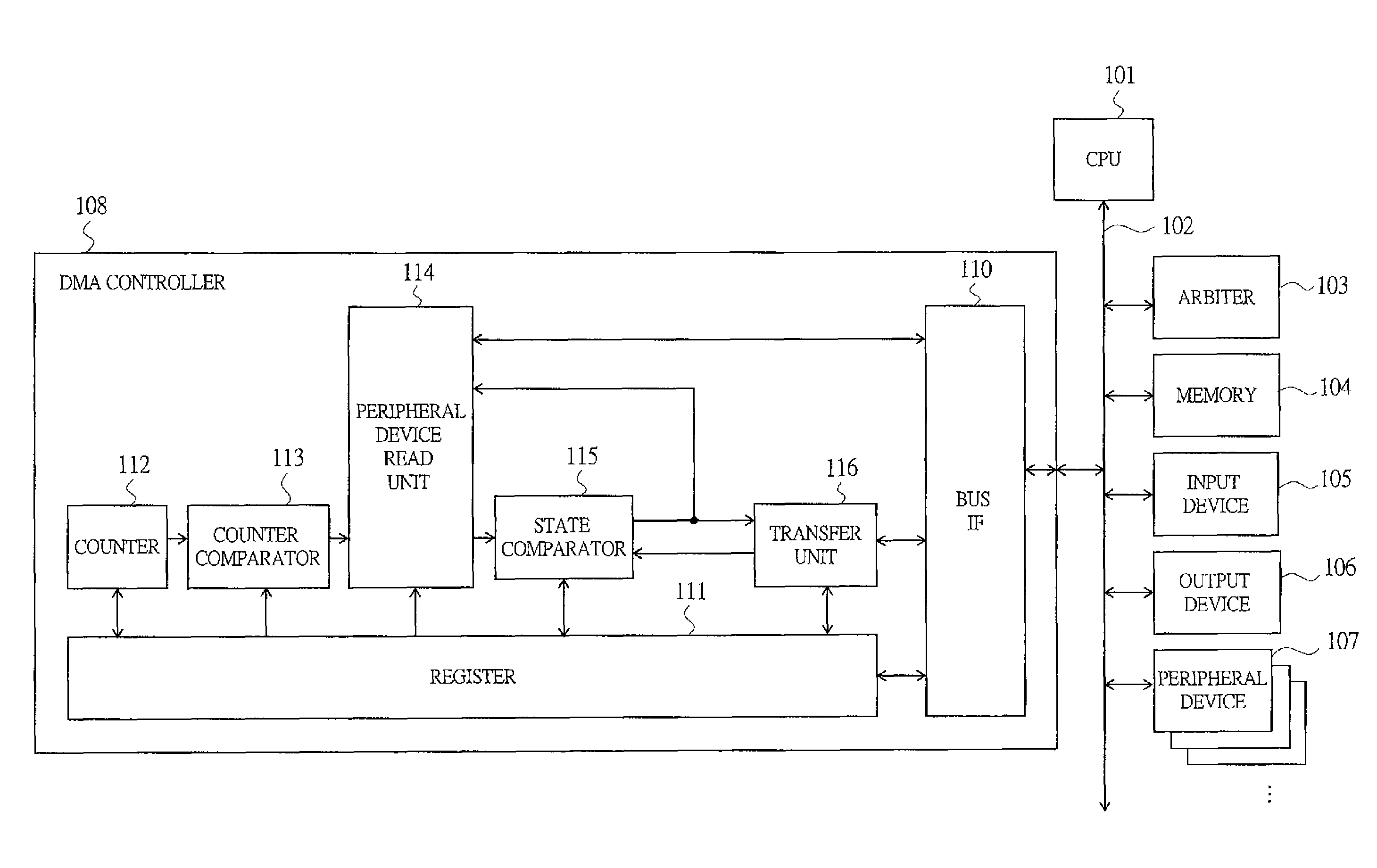
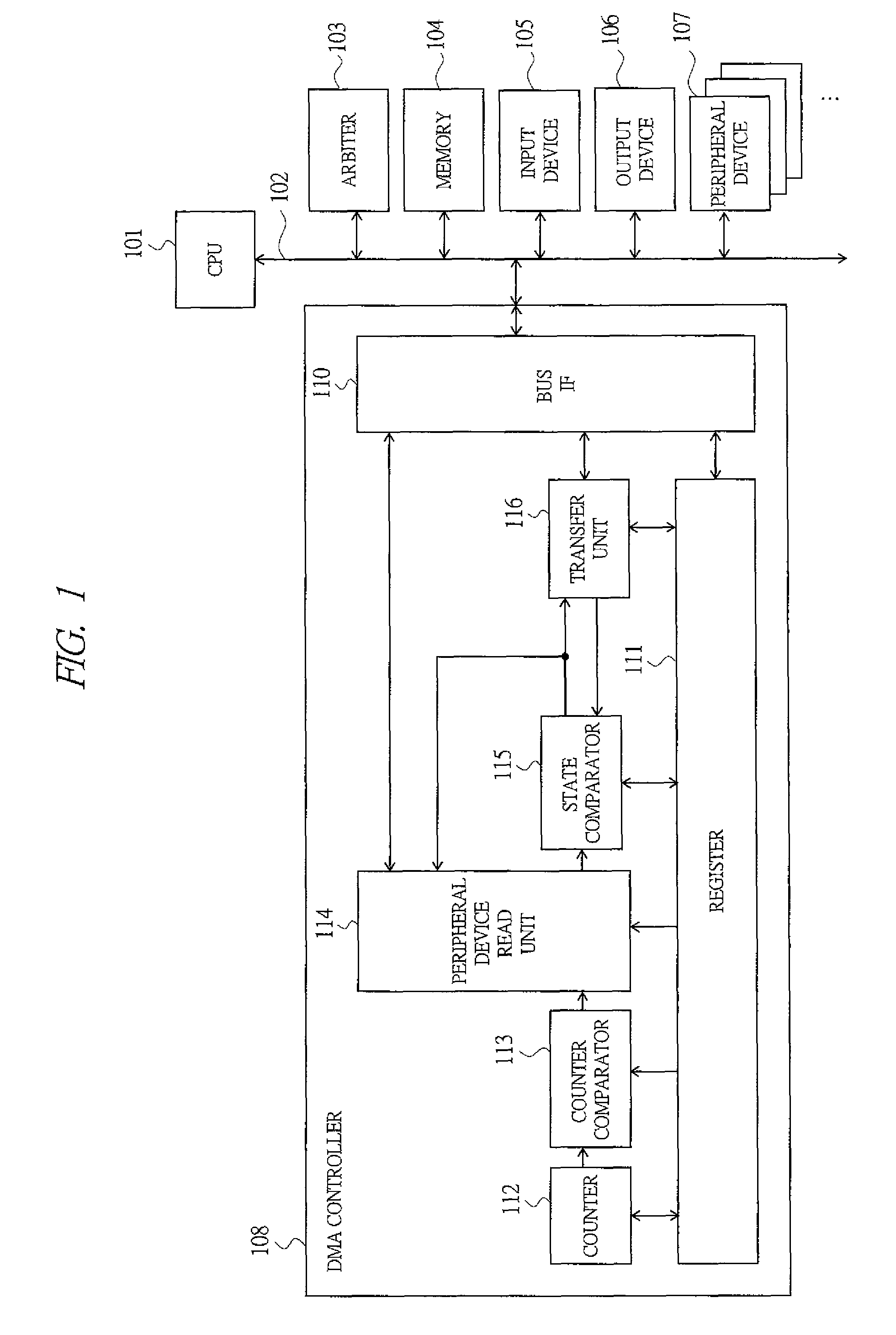
[0046]FIG. 1 is a function block diagram illustrating a configuration of a computer system mounting the DMAC according to the present embodiment. In FIG. 1, the computer system is configured to have a CPU 101, a bus 102, an arbiter 103, a memory 104, an input device 105, an output device 106, a peripheral device 107, and a DMAC 108.

[0047]The CPU 101 manages and controls respective devices of the arbiter 103, the memory 104, the input device 105, the output device 106, the peripheral device 107, and the DMAC 108 via the bus 102. The arbiter 103 arbitrates use requests of the bus 102 from the CPU 101, the memory 104, the input device 105, the output device 106, the peripheral device 107, and the DMAC 108. The memory 104 stores a program which the CPU 101 executes and / or data. The input ...

second embodiment

[0117]A DMA controller with peripheral device state confirmation function (hereinafter, called “DMAC”) of a second embodiment of the present invention will be described with reference to FIGS. 9 and 10.

[0118]FIG. 9 is a function block diagram illustrating a configuration of a computer system mounting the DMAC according to the present embodiment. The DMAC 108 according to the present embodiment has a configuration in which a peripheral device write unit 117 is added to the DMAC 108 illustrated in FIG. 1 of the first embodiment.

[0119]The peripheral device write unit 117, upon start or after end of a DMA transfer, performs a peripheral device write procedure for performing write to a register of the memory 104 and / or the peripheral device 107 in accordance with contents of instruction of the register 111 set by the CPU 101. In this manner, the DMAC 108 according to the present embodiment can perform not only confirmation of the state(s) of the peripheral device 107 and / or the program w...

third embodiment

[0161]A DMA controller with peripheral device state confirmation function (hereinafter, called “DMAC”) of a third embodiment of the present invention will be described with reference to FIG. 11. The DMAC according to the present embodiment handles DMA transfers in a plurality of cycles and among a plurality of peripheral devices.

[0162]A configuration of a computer system mounting the DMAC according to the present embodiment is the same with that in FIG. 1 of the first embodiment or that in FIG. 9 of the second embodiment.

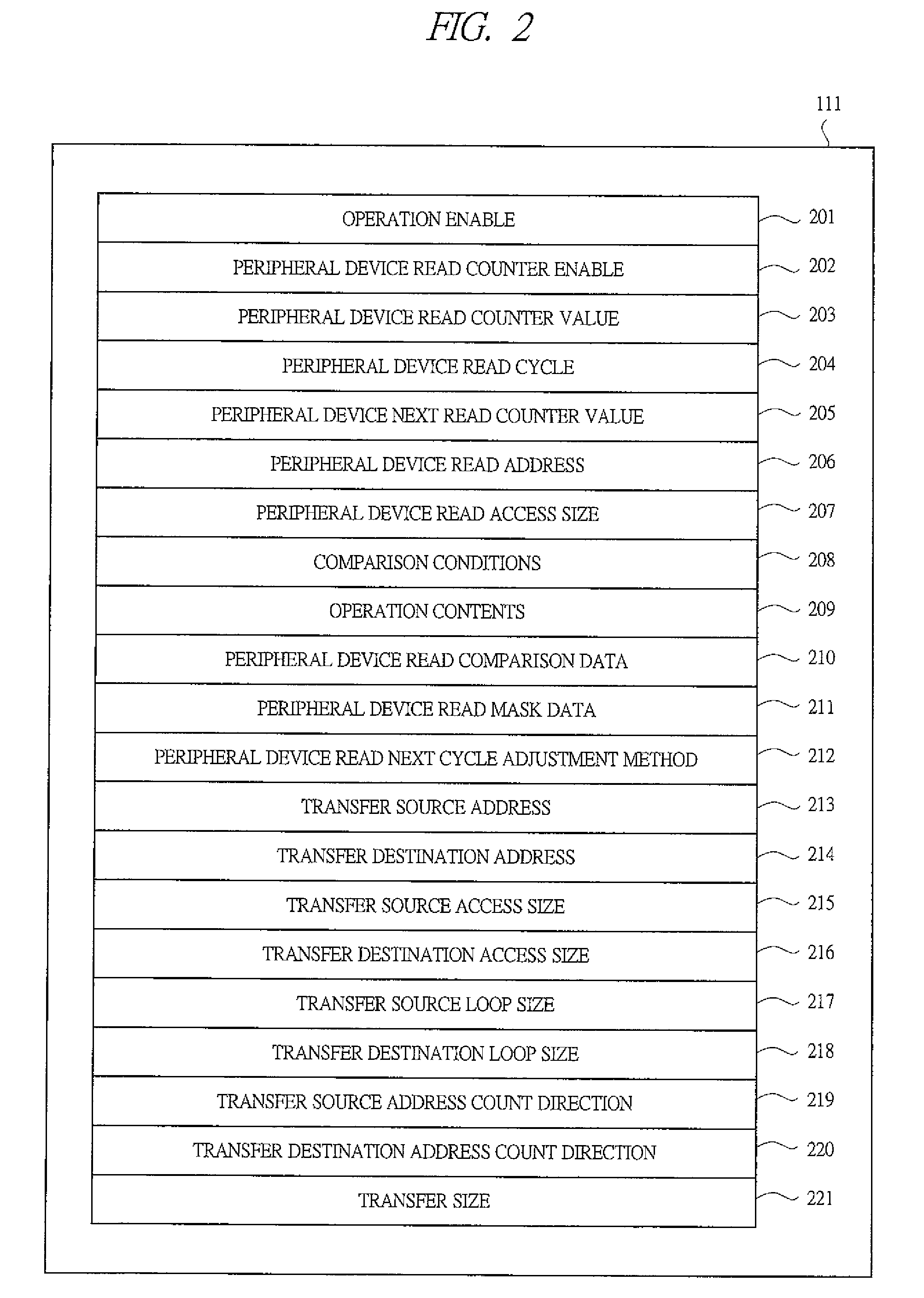
[0163]FIG. 11 is a diagram illustrating a configuration of registers which the register 111 has in the DMAC 108 in the case of using the configuration in FIG. 9 of the second embodiment. In the DMAC 108 according to the present embodiment, to define a second periodic transfer, respective registers of a peripheral device read cycle register 304 to a transfer size register 321, and a peripheral device write method register 331 to a peripheral device write mask data re...


PUM


Abstract

A DMA controller achieving real-time control of a DMA transfer relating to periodically operated peripheral devices at a low cost and with low power consumption. A typical embodiment of the invention is a DMA controller having: a counter for counting time; a counter comparator comparing a value of the counter and a counter value indicating an expected time of a DMA transfer; a peripheral device read unit reading a register of the peripheral device to acquire a state of a peripheral device by; and a state comparator comparing a value of the register read by the peripheral device read unit and a start condition of the DMA transfer, in which, with being triggered by establishment of a comparison result by the counter comparator, in accordance with a specified order, a processing of updating the counter value indicating the expected time of a DMA transfer to a value indicating a next expected time, a read of the register of the peripheral device by the peripheral device read unit, a comparison by the state comparator, and a DMA transfer on the condition that the comparison result by the state comparator is established are executed.

Description

TECHNICAL FIELD[0001]The present invention relates to a DMA controller which performs data transfer among peripheral devices handling multimedia data in a computer system, for example, a technique effectively applied to a technique for performing storage for storing image, audio, metadata relating to them, and data transfer between audio decoders efficiently and without increasing a load on a CPU.BACKGROUND ART[0002]In these years, as computer systems have become widely used, needs for technique of efficiently performing processing of multimedia data including audio, video, and the like have been growing. Multimedia processing is a repeat of simple data transfers, which is required to have high real-time property and throughput. Thus, the direct memory access system (DMA system) has been employed for the multimedia processing instead of the program I / O control system (PIO control system) which places a large load on a CPU.[0003]In a conventional computer system having a CPU, a memor...

Claims


Application Information

Patent Timeline
Patent Type & Authority Patents(United States)
IPC IPC(8): G06F13/28G06F13/00
CPCG06F13/28Y02B60/1228Y02D10/00
Inventor NAGAI, YASUSHINAKAGOE, HIROSHITAIRA, SHIGEKI
Owner RENESAS ELECTRONICS CORP
Why Eureka
Try Eureka