Method and device for automatic systems designed to operate movable barriers

a technology of automatic systems and control devices, applied in the direction of program control, ways, instruments, etc., can solve the problems of low production and sales costs, complex and costly means for connecting, and achieve the effects of low production and sales costs, complex and costly manufacturing, management and assembly of said connection means

Inactive Publication Date: 2012-05-15
NICE SPA
View PDF44 Cites 19 Cited by
  • Summary
  • Abstract
  • Description
  • Claims
  • Application Information

AI Technical Summary

Benefits of technology

[0019]The object of the present invention is to provide a safety device for automatic systems designed to operate movable barriers, which eliminates the disadvantages of the present state of the art.
[0021]A control device for movable barriers according to the method of the invention allows the transmission of different signals, incorporating a transmission protocol consisting of more than two signal configurations having different coded meanings. The status of a sensor (for example a sensing edge), which is fixed to a movable barrier, is transmitted to the barrier control and operating unit without having to employ complex and costly cable connections.

Problems solved by technology

Said safety devices are generally composed of infrared photocells and sensing edges (active pressure-sensitive components) which are very common because they result in low production and sales costs and also ensure the necessary level of safety required by the regulations.
Since the sensing edge must be fixed to the end of the movable barrier which reaches a fixed end-of-travel point, it is required to provide complex and costly means for connecting together the sensing edge and the electric and electronic system.
The manufacture, management and assembly of said connection means is complex and costly.
Moreover they are difficult to produce with an aesthetically pleasing form.
In the event of pressure against the sensing edge, the transmitter interrupts the transmission of the continuous signal to the receiver, and the control unit interprets this interruption in the signal as being an emergency condition, causing the immediate stoppage and reversal in the movement of the movable barrier.
In fact:the control device, and in particular the transmitter, is characterized by a high power consumption since it must transmit a continuous signal in order to avoid waiting times which may result in stoppage of the system;the technology used to manufacture standard batteries does not guarantee a minimum working period of a few months for the system, unless large-size batteries are used, with the consequent problem of where to house them;the device does not alert the user when the charging level of the battery is low so that it may be replaced in due time;the transmitter is able to encode a single type of message (one piece of information), with the risk that the receiver may be disturbed by a signal similar to that emitted by the transmitter (for example by another transmitter positioned incorrectly).
This condition may result in the device assuming a “non safety” condition because a possible danger message may be wrongly interpreted or not be detected at all.

Method used


Image

  • Method and device for automatic systems designed to operate movable barriers
  • Method and device for automatic systems designed to operate movable barriers
  • Method and device for automatic systems designed to operate movable barriers

Examples


Embodiment Construction

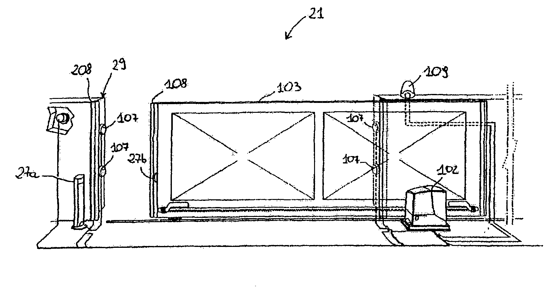
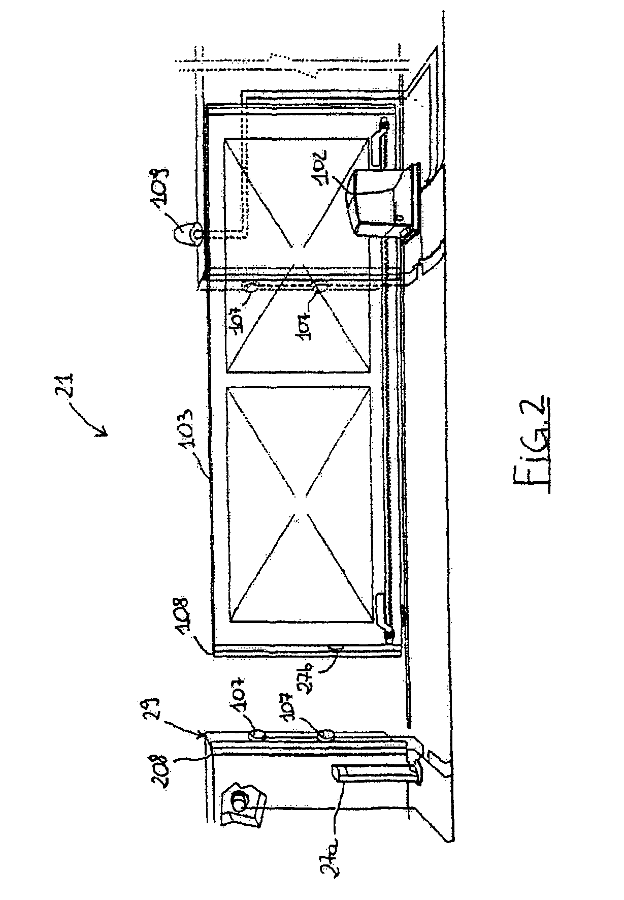
[0028]With reference to FIG. 2 (reference numbers the same as those in FIG. 1 indicate similar parts) this shows a control device 21 according to the invention, comprising a pair of photocells 27a, b. The first photocell 27a is a receiving photocell and is situated in the vicinity of an end-of-travel point 29 of the barrier 103; the second photocell 27b is a transmitting photocell and is positioned at the end of the barrier 103, close to a sensing edge 108 and connected thereto via traditional electric and electronic means (not shown). Another sensing edge 208 is positioned at the end-of-travel point 29 and is controlled in a known manner by a unit (not shown) controlling the barrier 103.

[0029]The photocell 27b (see FIG. 4) is essentially composed of wireless means 41 for the transmission of (preferably infrared) pulses and associated driving stages 41 controlled by a microcontroller unit 42 which also processes the information sent by:[0030]a vibration movement sensor 43 of the kno...


PUM


Abstract

Method, together with the devices implementing said method, for controlling the closing and opening movements of a movable barrier (103) so as to prevent a dangerous impact with an obstacle or crushing thereof, said movable barrier (103) comprising a closing edge having, positioned thereon, one or more sensors (108) connected to a first transceiver (27b) able to exchange a signal with a second fixed transceiver (27a) in communication with a control unit which manages the movement of the barrier (103), comprising a step defining for said signal a communications protocol consisting of more than two signal configurations (A, B, C, D).

Description

[0001]This application is a National Phase Application of International Application No. PCT / EP2005 / 055722, filed Nov. 3, 2005, which claims the benefit under 35 U.S.C. 119 (a-e) of Italian Application No. TV2004A000128 filed Nov. 10, 2004, which is herein incorporated by reference.BACKGROUND OF THE INVENTION [0002]1. Field of the Invention[0003]The present invention relates to a method and a control device for automatic systems designed to operate movable barriers, in particular doors, shutters and gates.[0004]2. Description of the Related Art[0005]In order to comply with existing safety regulations for electric and electronic systems designed to operate and manage movable barriers such as gates, doors and automatic shutters, certain types of safety devices have been widely adopted. Said safety devices are generally composed of infrared photocells and sensing edges (active pressure-sensitive components) which are very common because they result in low production and sales costs and ...

Claims


Application Information

Patent Timeline
Patent Type & Authority Patents(United States)
IPC IPC(8): E06B3/00
CPCE05Y2400/452E05Y2400/512E05Y2400/59E05Y2400/612E05Y2400/662E05Y2400/822E05Y2600/45E05Y2600/46E05Y2800/21E05Y2800/22E05Y2900/40G07C9/00182G07C2009/00928E05F15/00E05Y2400/44E05Y2400/61E05Y2900/106E05Y2201/434E05Y2600/452E05F15/40E05F15/42E05F15/43E05F15/635E05F2015/437E05F15/632E05Y2400/54G05B2219/45242E05F2015/436E05Y2400/334G05B2219/33261
Inventor MARCHETTO, OSCAR
Owner NICE SPA
Why Eureka
Try Eureka