Scroll-type fluid displacement apparatus with improved cooling system

a fluid displacement apparatus and rolling type technology, applied in the direction of liquid fuel engines, rotary/oscillating piston pump components, machines/engines, etc., can solve the problems of low heat dissipation efficiency of heat pipes, weak cooling air flow inside the passage of the drive shaft, and critical heat removal efficiency of compression process, etc., to achieve efficient heat transfer, maximize heat transfer, and maximize air flow and forced

Active Publication Date: 2012-05-15
ADVANCED SCROLL TECH HANGZHOU
View PDF20 Cites 8 Cited by
  • Summary
  • Abstract
  • Description
  • Claims
  • Application Information

AI Technical Summary

Benefits of technology

[0010]A scroll-type fluid displacement apparatus is described with a compact axial cooling system to cool scrolls, bearings and the motor. In this cooling system, at least one axial cooling fan draws air from the front end of the compressor. The cooling air flows along the surface of the compressor parts via axial air channels and is blown out by the fan at the rear end of the compressor to maximize the air flow and forced convection heat transfer.
[0011]A heat pipe mechanism is also described. In this mechanism, multiple heat pipes are installed in the fixed and orbiting scroll members as well to maximize heat transfer from the inside bodies of parts to the condenser sides of the heat pipes. The condenser sides of the heat pipes are directly exposed to the cooling air flowing in the cooling air channels, to efficiently transfer heat from inside of the parts in the apparatus to the cooling air for maximum heat dissipation.

Problems solved by technology

However, the efficient removal of heat generated in the compression process is critical.
First, the cooling fans directly blow cooling air to nearby endplates of stationary scroll members.
Second, there are at most two heat pipes which can be installed in the central region of the drive shaft and the heat pipe condensers cannot be well cooled by cooling air because they are located inside the drive shaft that leads to low heat dissipation efficiency of the heat pipes.
In other words, the cooling air flow inside the passage of the drive shaft is weak.
This makes the heat dissipation from scroll members to the cooling air inefficient.
In addition, this cooling system does not provide cooling to the motor which usually need a separate cooling system.
However, the cooling fan system interrupts the motor shaft and the scroll driving shaft which will cause alignment difficulty.
Furthermore, due to the zigzag of the cooling air passages, the cooling air experiences tremendous pressure loss that will seriously reduce the cooling air flow rate.
This arrangement of air passages creates significant pressure resistance to the fan and reduces the cooling air flow rates.

Method used


Image

  • Scroll-type fluid displacement apparatus with improved cooling system
  • Scroll-type fluid displacement apparatus with improved cooling system
  • Scroll-type fluid displacement apparatus with improved cooling system

Examples


Embodiment Construction

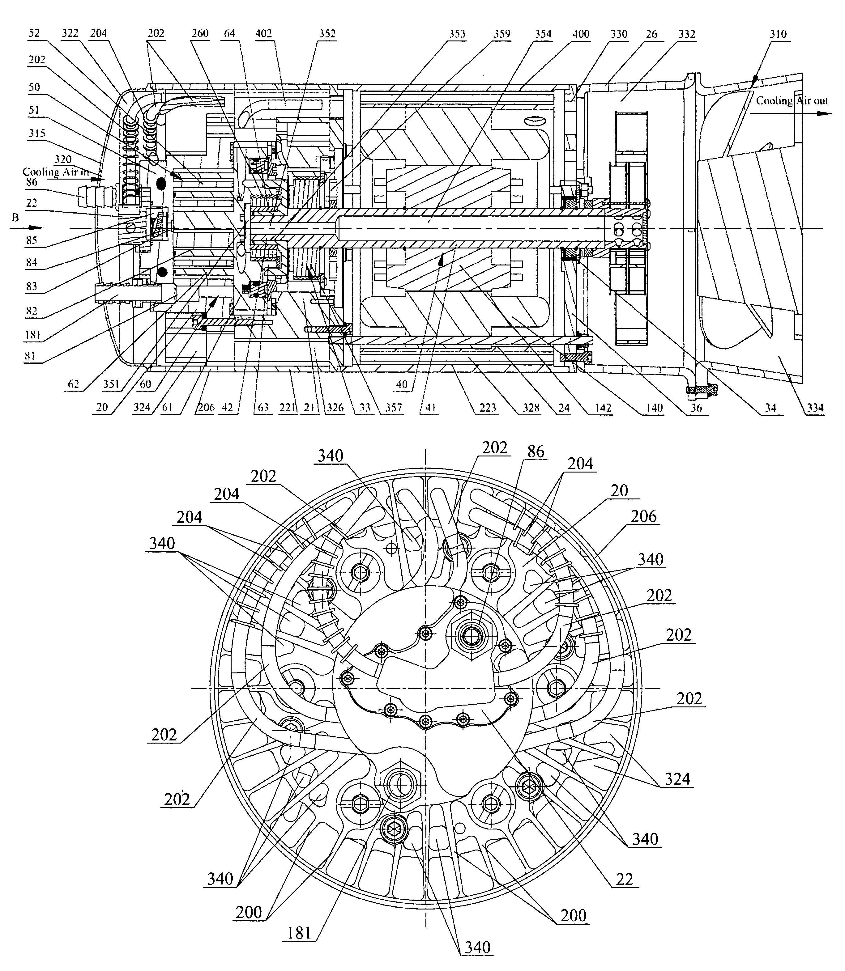
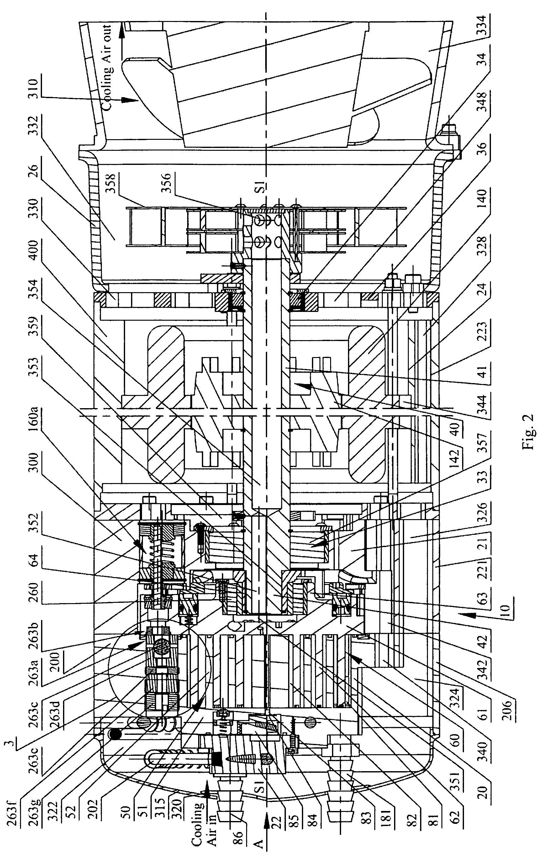
[0026]Referring to FIGS. 2 and 5, a fully compliant floating scroll air compressor with an axial cooling system is shown. Air compressor unit 10 includes a main housing 20, base housing 21, motor housing 24, rear bearing plate 36, crankshaft 40, fixed scroll 50 and orbiting scroll 60. The crankshaft 40 includes a central rod 41 and a crank pin 42. The central rod 41 is rotatably supported by bearings 33 and 34, and rotates about its axis S1-S1. The fixed scroll member 50 has an end plate 51 from which a scroll element 52 extends. The orbiting scroll member 60 includes a circular end plate 61, a scroll element 62 affixed to and extending from the end plate 61, and orbiting bearing hub 63 affixed to and extending from the central portion of the end plate 61. There is a crank pin bearing 260 inside the bearing hub 63. Scroll elements 52 and 62 are interfitted at an 180 degree angular offset, and at a radial offset having an orbiting radius Ror during operation. At least one sealed off ...


PUM


Abstract

An axial air cooling system for scroll-type positive fluid displacement apparatus provides needed cooling. The system includes an axial fan and centrifugal pump and internal cooling air channels inside parts integrating main housing, base housing and motor housing with their corresponding shell parts by cooling fins. The cooling air channel also includes passages inside the orbiting scroll, shaft central hole and gaps inside stator slots and winding. Heat pipes are installed inside the fixed and orbiting scrolls to conduct heat from inside of the apparatus to the peripheral condenser portion of the heat pipes to be cooled by the cooling air.

Description

FIELD[0001]This disclosure relates to a scroll-type positive fluid displacement apparatus and more particularly to a scroll-type apparatus having an improved cooling system.BACKGROUND[0002]There is known in the art a class of devices generally referred to as “scroll” pumps, compressors and expanders, wherein two interfitting spiroidal or involute spiral elements are conjugate to each other and are mounted on separate end plates forming what may be termed as fixed and orbiting scrolls. These elements are interfitted to form line contacts between spiral elements.[0003]A pair of adjacent line contacts and the surfaces of end plates form at least one sealed off pocket. When one scroll, i.e. the orbiting scroll, makes relative orbiting motion, i.e. circular translation, with respect to the other, the line contacts on the spiral walls move along the walls and thus change the volume of the sealed off pocket. The volume change of the pocket will expand or compress the fluid in the pocket, d...

Claims


Application Information

Patent Timeline
Patent Type & Authority Patents(United States)
IPC IPC(8): F01C21/06F01C1/063F04C29/04F01C1/02
CPCF04C18/0253F04C18/0215F04C29/04F04C23/008F04C2240/30
Inventor NI, SHIMAO
Owner ADVANCED SCROLL TECH HANGZHOU
Why Eureka
Try Eureka