Apparatus for detecting vital functions, control unit and pulse wave sensor

a technology for vital functions and apparatus, applied in the field of devices for detecting vital functions, can solve the problems of low detection accuracy, inability to easily measure cough and the like in private homes or vehicles, and complicated measuring devices and measuring methods

Active Publication Date: 2012-05-15
SHIOMI TOSHIAKI +1
View PDF16 Cites 17 Cited by
  • Summary
  • Abstract
  • Description
  • Claims
  • Application Information

AI Technical Summary

Benefits of technology

[0022]Namely, the minimum blood pressure (the diastolic blood pressure) is maintained by the elasticity of blood vessels, and it does not happen that the amplitude on p-diastole side suddenly becomes lower than the lower-limit level as observed based upon the pulse wave signals. If a signal of a pulse wave lower than the diastolic blood pressure appears, therefore, it is regarded that the motion artifact has occurred. In the diagram illustrating the pulse waves, the upper side is expressed to be the side of systole and the lower side is expressed to be the side of diastole for easy comprehension relative to the blood pressure (diagram which is usually called inverted pulse waves).
[0075]This prevents the pulse wave sensor from pushing the skin with an excess of pressure. Therefore, an excess of load is not given to the skin, the waveforms of pulses are not distorted, and the pulse waves can be accurately measured.

Problems solved by technology

These measuring devices and measuring methods are so complicated that the cough and the like cannot be easily measured in private homes or vehicles.
The accuracy of detection is low due to noise, and it is difficult to specify the source of sound when there is a plurality of persons.
Therefore, the hand becomes a blind which lowers the accuracy of detection.
This method requires a complicated measuring device.

Method used


Image

  • Apparatus for detecting vital functions, control unit and pulse wave sensor
  • Apparatus for detecting vital functions, control unit and pulse wave sensor
  • Apparatus for detecting vital functions, control unit and pulse wave sensor

Examples


Embodiment Construction

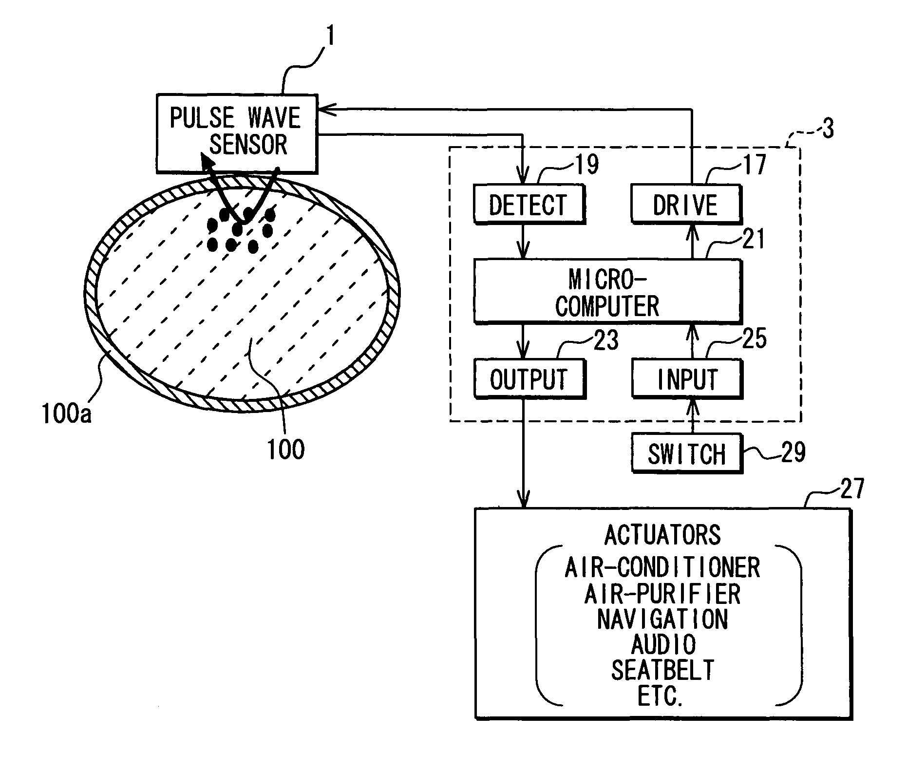
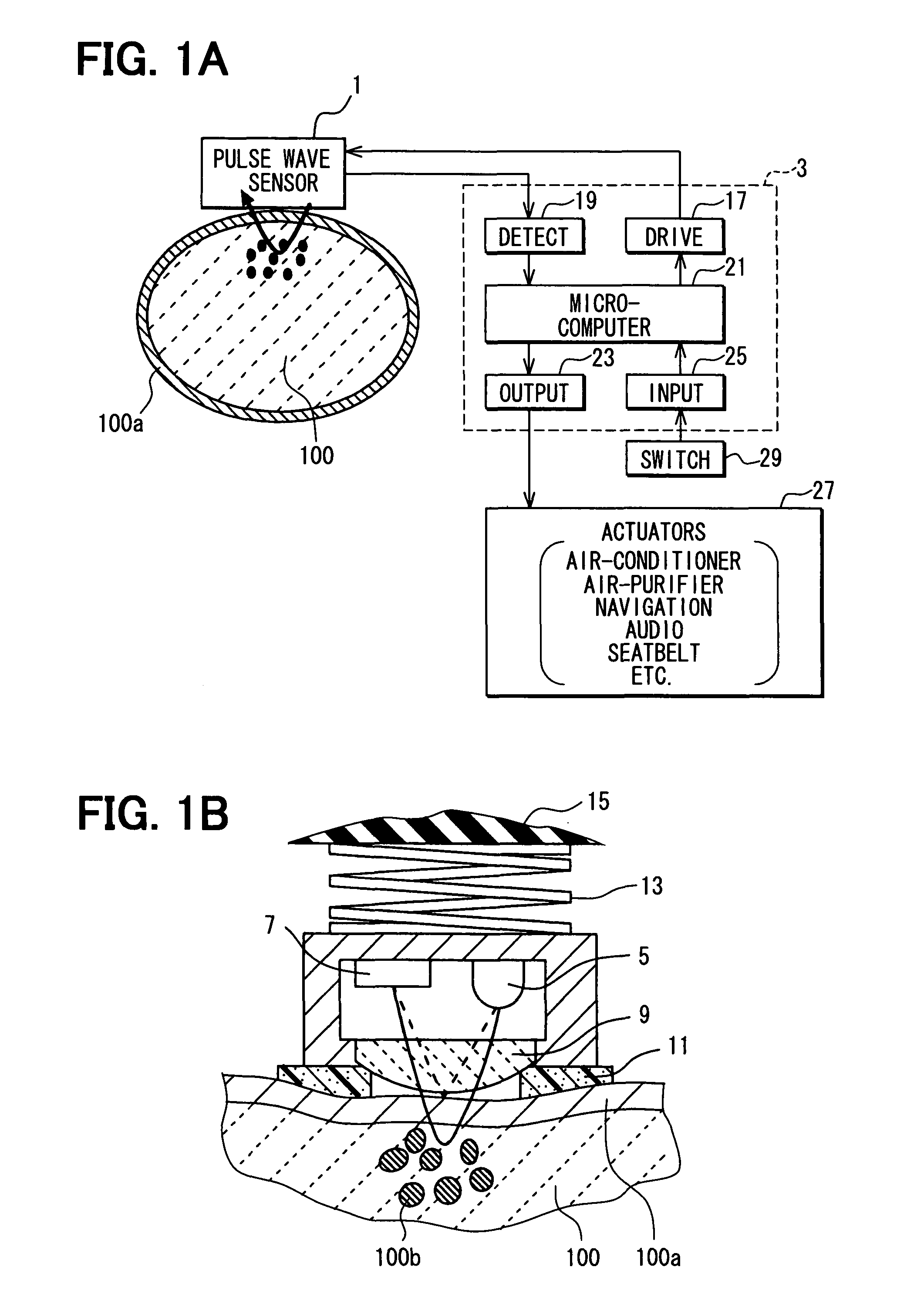
[0091]First, a biometric detection apparatus for detecting conditions of a body is described with reference to one embodiment shown in FIGS. 1A and 1B. The apparatus detects vital functions such as cough or yawn by using a pulse wave sensor 1. This sensor 1 is attached to a portion of a human body 100 such as a finger, a palm or a wrist, where motion is small. The apparatus further uses a control unit 3, which drives the pulse wave sensor 1 and processes the outputs from the pulse wave sensor 1.

[0092]Here, the pulse wave sensor 1 is an optical sensor of the reflection type (opto-capacitive pulse wave sensor) comprising a light-emitting element (e.g., light-emitting diode: green LED) 5, a light-receiving element (e.g., photodiode: PD) 7, and a transparent lens 9 which permits light to pass through and also efficiently receives light.

[0093]The pulse wave sensor 1 has a ring-like buffer member (e.g., a sponge having a rugged end) 11 that serves as a spacer surrounding the lens 9 on the...


PUM


Abstract

An apparatus for detecting vital functions has a pulse wave sensor attachable to a body and a control unit. The control unit checks if amplitude of pulse wave signals produced from the pulse wave sensor varies. The control unit further checks if a large change in the amplitude during a systolic phase of a pulse wave corresponding to the systolic phase of the heart. If a first large change in the amplitude during a diastolic phase of a pulse wave corresponding to the diastolic phase of the heart, it is highly probable that a motion artifact has occurred. Therefore, a motion artifact flag is set. Next, it is checked if the amplitude in the next diastole is changing by more than 30%. if it is presumed that the occurrence of cough is highly probable, a cough flag is set. if it is neither the motion artifact nor the cough, then a yawn flag is set.

Description

CROSS REFERENCE TO RELATED APPLICATION[0001]This application is based on and incorporates herein by reference Japanese Patent Application No. 2006-152354 filed on May 31, 2006.FIELD OF THE INVENTION[0002]This invention relates to a device for detecting vital functions, that is, biometric conditions, such as cough and yawn by using a pulse wave sensor that is easy to mount.BACKGROUND OF THE INVENTION[0003]A nasal thermistor, a nasal pressure sensor, a chest-band sensor and the like are respiratory system monitors for detecting breathing (respiration), cough and yawn.[0004]As for measuring, for example, the cough, various devices using a spiro-breathing flow meter (patent document 1), signals of the thyroid (patent document 2) and vibration of a catheter (patent document 3). These measuring devices and measuring methods are so complicated that the cough and the like cannot be easily measured in private homes or vehicles.[0005]As simpler technologies, it is proposed to use a pattern of...

Claims


Application Information

Patent Timeline
Patent Type & Authority Patents(United States)
IPC IPC(8): A61B5/02
CPCA61B5/0059A61B5/02416A61B5/087A61B5/6826A61B5/6838A61B5/0823
Inventor NANBA, SHINJISHIOMI, TOSHIAKI
Owner SHIOMI TOSHIAKI
Why Eureka
Try Eureka