Axial flux alternator with air gap maintaining arrangement

a technology of air gap and alternator, which is applied in the direction of motors, wind energy generation, dynamo-electric machines, etc., can solve the problems of lower rpm of wind turbines, energy losses, and higher weight and maintenance, and achieve high voltage dc

Inactive Publication Date: 2012-05-15
MELLER MOSHE
View PDF76 Cites 27 Cited by
  • Summary
  • Abstract
  • Description
  • Claims
  • Application Information

AI Technical Summary

Benefits of technology

[0013]The dimensions or diameters of the rolling elements fix the distance between the rotating disks and thereby set and operationally maintain an air gap between the surfaces of the magnets in the magnetic disk and the surfaces of the magnetic cores of the electromagnetic assemblies of the coil disk. Maintaining this air gap prevents the magnets on the magnetic disk from coming into contact with the magnetic cores on the coil disk and thereby allowing continuous motion and use of the wind turbine arrangement including the alternator.
[0015]In any of the axial flux generator in accordance with the invention, the magnetic and / or coil disks may be constructed to enable them to be lightweight yet strong. Specifically, ultra light and strong large diameter magnetic and coil disks for axial flux generators each include thin outer layers of strong, rigid materials and a thicker inner layer or core of airy light-weight core materials. While the outer layers and inner layer of the magnetic disks can be constructed from conductive materials, the outer layers and inner layer of the coil disks must be constructed from non-conductive materials. Supporting elements can be placed within the inner layers to strengthen the disks.
[0016]Another embodiment of an axial flux generator in accordance with the present invention comprises a large number of magnets arranged in rows on the magnetic disk(s), with each magnetic row being separated from adjacent magnetic rows by constant angular distance, and a large number of electromagnetic coil bobbins arranged on the coil disk, with each coil bobbin including a magnetic core and a conductive coil wound around it. Each coil bobbin is separated from adjacent coil bobbins by a constant angular distance. The coil disk and the magnetic disk(s) face each other. There is a strong magnetic attraction between the magnets and the magnetic cores in the coil bobbins. If all magnets and magnetic cores are at maximum magnetic attraction at certain angular positions, locking forces would be induced on the magnetic disks and the coil disk which would make the relative rotational motion between the generator disks impossible. To avoid this situation, in this embodiment of the axial flux generator, the angular distances between the magnetic rows on the magnetic disk(s) and the coil bobbins on the coil disk is designed so that only a small portion of the magnets and the coil bobbins can be at maximum magnetic attraction in certain angular position. This design allows smooth rotational motion between the magnetic disks and the coil disks and the large number of electrically autonomous coil bobbins to be electrically connected so that the output of the generator can be high voltage DC.

Problems solved by technology

This, in turn, leads to lower RPM of the wind turbine.
Some of the main disadvantages of this type of transmission gear section or gearbox include: energy losses, lower overall efficiency, and higher weight and maintenance.
Reliability issues with wind turbine gearboxes are known to exist and stem, for example, from the extreme engineering challenges that gearbox technology faces in wind applications.
Constructing the alternator to provide a desired dimension for the air gap between the magnets and the coils of an axial flux alternator, also referred to herein as adjusting the air gap, and maintaining the air gap during operation of the wind turbine, is a technical challenge, particularly for a large diameter axial flux alternator.
Another issue of concern for wind turbines is that large wind turbine span leads to a lower RPM's.
Consequently, direct drive generators are very heavy.
At such weights, problems rapidly develop with transportation and installation, particularly with the availability of lifting ships capable of deploying such weights in an offshore environment.
This, in turn, can lead to dramatic increases in offshore wind project installation costs as well as the overall cost effectiveness of such a project.
Furthermore, in order to achieve sufficient frequency with low RPM's, a relatively large number of magnets is required.
For projects located far from the grid connection point, or of several hundred megawatts in capacity, AC transmission becomes costly or impossible, due to cable-generated reactive power using up much of the transmission capacity.
Still another issue of concern for direct drive generators is that they are expected to reduce down time and maintenance cost.
However, as direct drive permanent magnet generators typically comprise neodymium-iron-boron elements, there are major concerns over how rare earth minerals could limit the development of direct drive wind turbine technologies.
For the sixth consecutive year, the Chinese Ministry of Industry and Information Technology has trimmed output quotas of rare earth metals, making the resource scarce and expensive.

Method used


Image

  • Axial flux alternator with air gap maintaining arrangement
  • Axial flux alternator with air gap maintaining arrangement
  • Axial flux alternator with air gap maintaining arrangement

Examples


Embodiment Construction

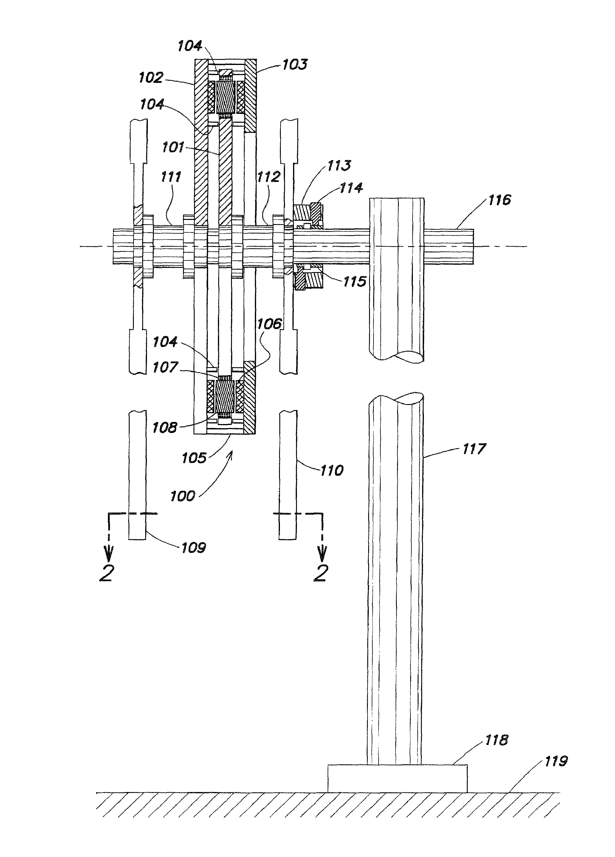
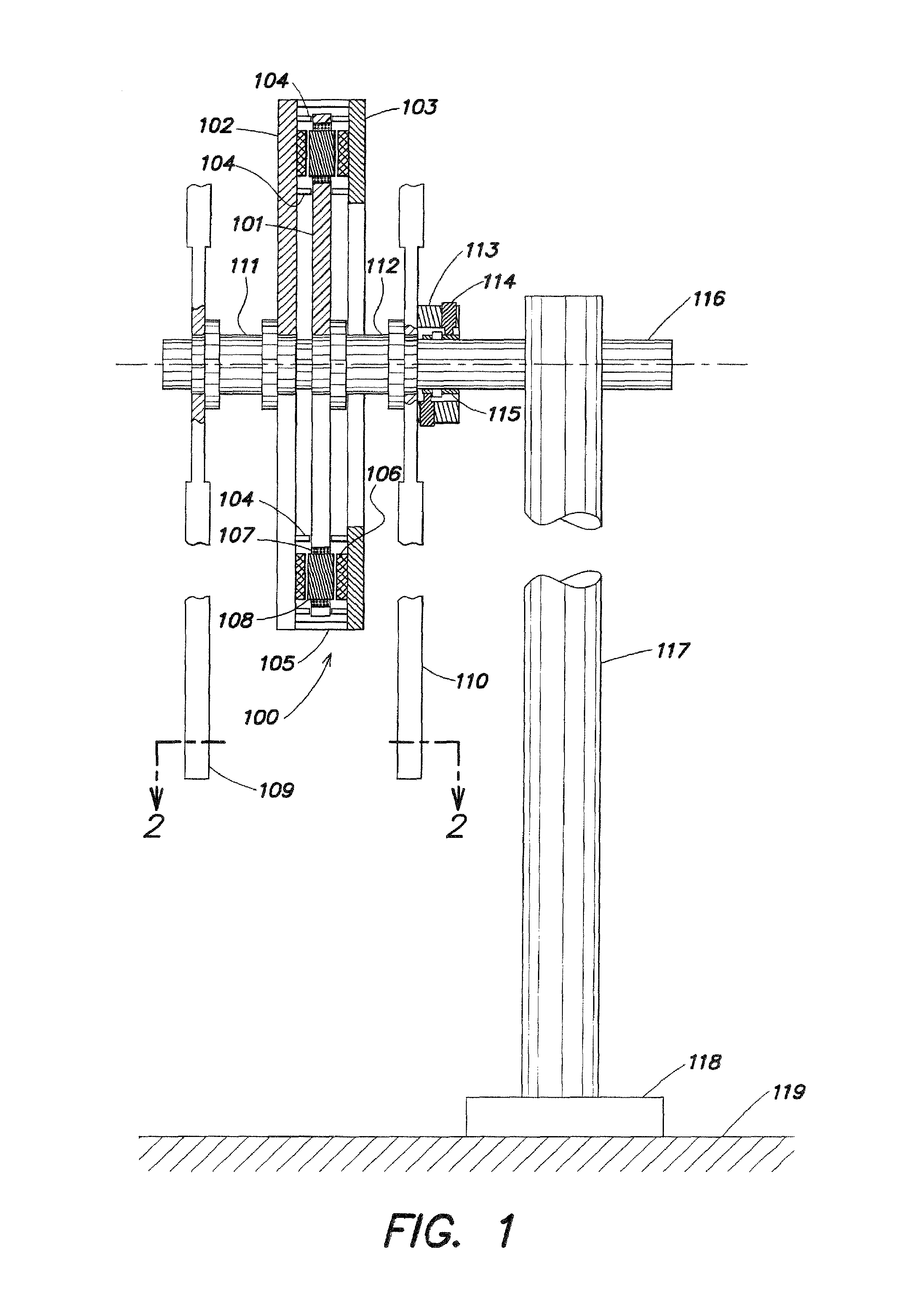
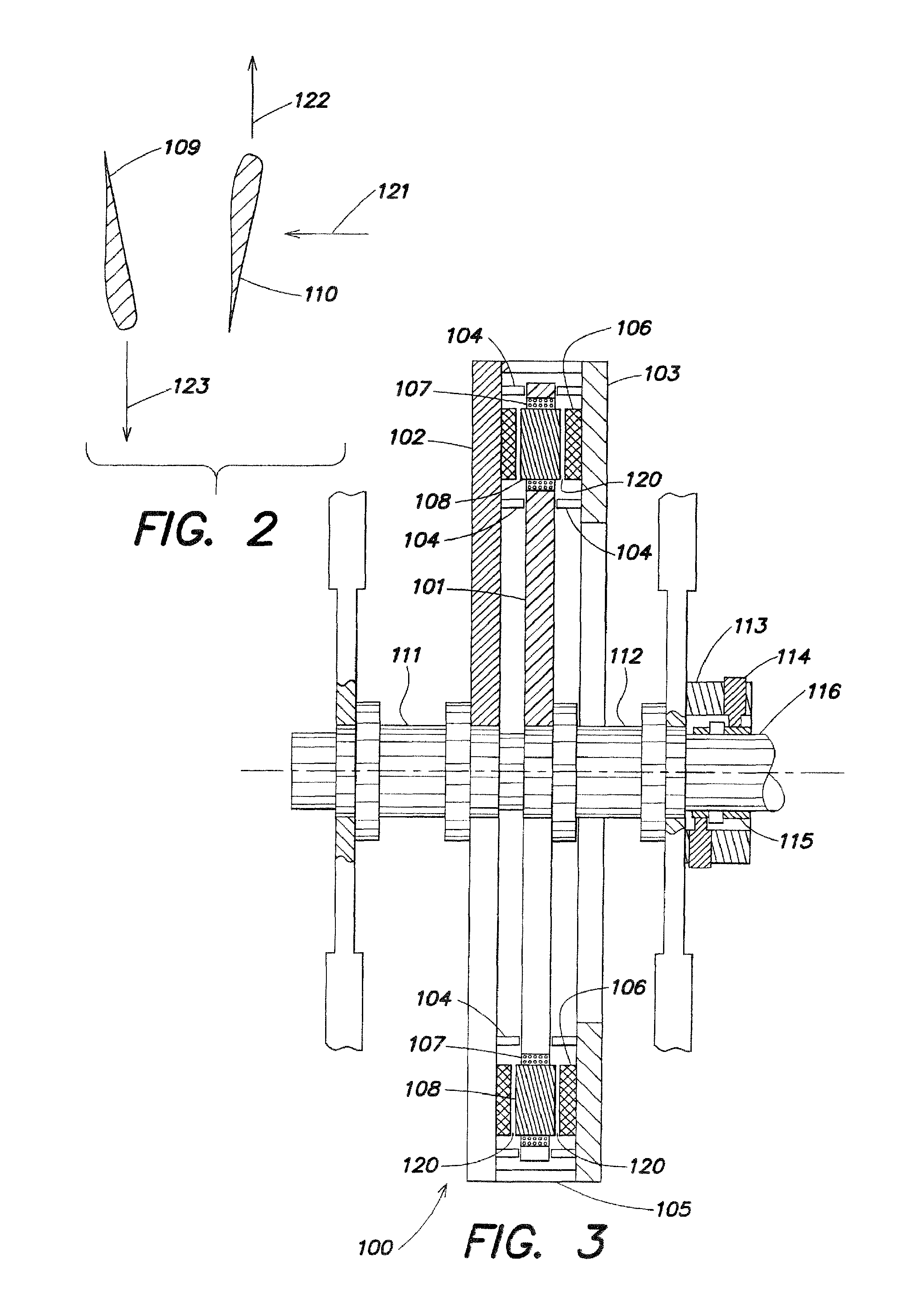
[0045]Referring to the accompanying drawings wherein like reference numerals refer to the same or similar elements, FIG. 1 shows a wind turbine arrangement including an axial flux alternator in accordance with the invention, designated generally as 100. As used herein, the term “alternator” is synonymous with and used interchangeably with a “generator”. The alternator 100, or alternator section, includes three disks, a coil disk 101, a main or primary magnetic disk 102 and a secondary magnetic disk 103. Supporting elements 105 mechanically connect the secondary magnetic disk 103 to the primary magnetic disk 102. Supporting elements 105 may be a plurality of rigid members distributed over the circumference of the primary and secondary disks 102, 103. Although three disks 101, 102, 103 are shown in FIG. 1, one of which is a coil disk and the other two of which are magnetic disks, at a minimum, the alternator section 100 includes one magnetic disk and one coil disk, see FIG. 11 describ...


PUM


Abstract

Axial flux alternator for a wind turbine arrangement includes at least one magnetic disk including magnets and at least one coil disk including electromagnetic assemblies. One or both disks are mounted to wind turbines such that adjacent disks rotate in opposite directions, or such that the magnets of a magnetic disk move relative to the electromagnetic assemblies of an adjacent coil disk which may move or be stationary, or vice versa. Between adjacent disks, rolling elements on one disk roll, slide or move on or against the surface of the opposite disk in order to fix and maintain air gaps between the magnets on a magnetic disk and magnetic cores of the electromagnetic assemblies on the coil disk, and thus enable continued motion and use of the alternator.

Description

CROSS REFERENCE TO RELATED APPLICATIONS[0001]This application is a continuation-in-part of U.S. patent application Ser. No. 12 / 980,589 filed Dec. 29, 2010 now U.S. Pat. No. 8,026,626, and claims priority under 35 U.S.C. §119(e) of U.S. provisional patent application Ser. Nos. 61 / 416,439 filed Nov. 23, 2010, 61 / 450,834 filed Mar. 9, 2011, 61 / 452,277 filed Mar. 14, 2011, and 61 / 452,858 filed Mar. 15, 2011, all of which are incorporated by reference herein.FIELD OF THE INVENTION[0002]The present invention relates to axial flux type alternators for wind turbine arrangements that include magnets and coils that must be spaced apart from one another by an air gap to maintain functionality of the wind turbine alternator. The present invention also relates to a method for providing for and maintaining functionality or operability of a wind turbine arrangement including an axial flux type alternator.BACKGROUND OF THE INVENTION[0003]The challenges of global climate change and energy security d...

Claims


Application Information

Patent Timeline
Patent Type & Authority Patents(United States)
IPC IPC(8): H02P9/00F03D9/00
CPCF03D1/025F03D9/002H02K1/14H02K5/1737H02K7/08H02K7/1838H02K21/24H02K7/088F05B2220/7066F05B2250/31Y02E10/725F03D9/25F03D80/70Y02E10/72
Inventor MELLER, MOSHE
Owner MELLER MOSHE
Why Eureka
Try Eureka