Electronic component module

a technology of electronic components and components, applied in the direction of printed circuit aspects, magnetic/electric field screening, electrical apparatus construction details, etc., can solve the problems of suppressing the reduction of handling performance of mounting machines, and achieve the effect of low elasticity, easy to be absorbed, and easy reduction of impact load applied to the electronic components (the first electronic component and the second electronic component)

Active Publication Date: 2012-05-15
SHARP KK
View PDF20 Cites 27 Cited by
  • Summary
  • Abstract
  • Description
  • Claims
  • Application Information

AI Technical Summary

Benefits of technology

[0012]The present invention is created for solving the above-mentioned problem, and it is an object of the present invention to provide an electronic component module which has high reliability and is capable of suppressing reduction of handling performance of the mounting machine, and to provide a method for manufacturing the electronic component module.

Problems solved by technology

Thus, it is possible to suppress reduction of handling performance of the mounting machine.

Method used


Image

  • Electronic component module
  • Electronic component module
  • Electronic component module

Examples


first embodiment

[0092](First Embodiment)

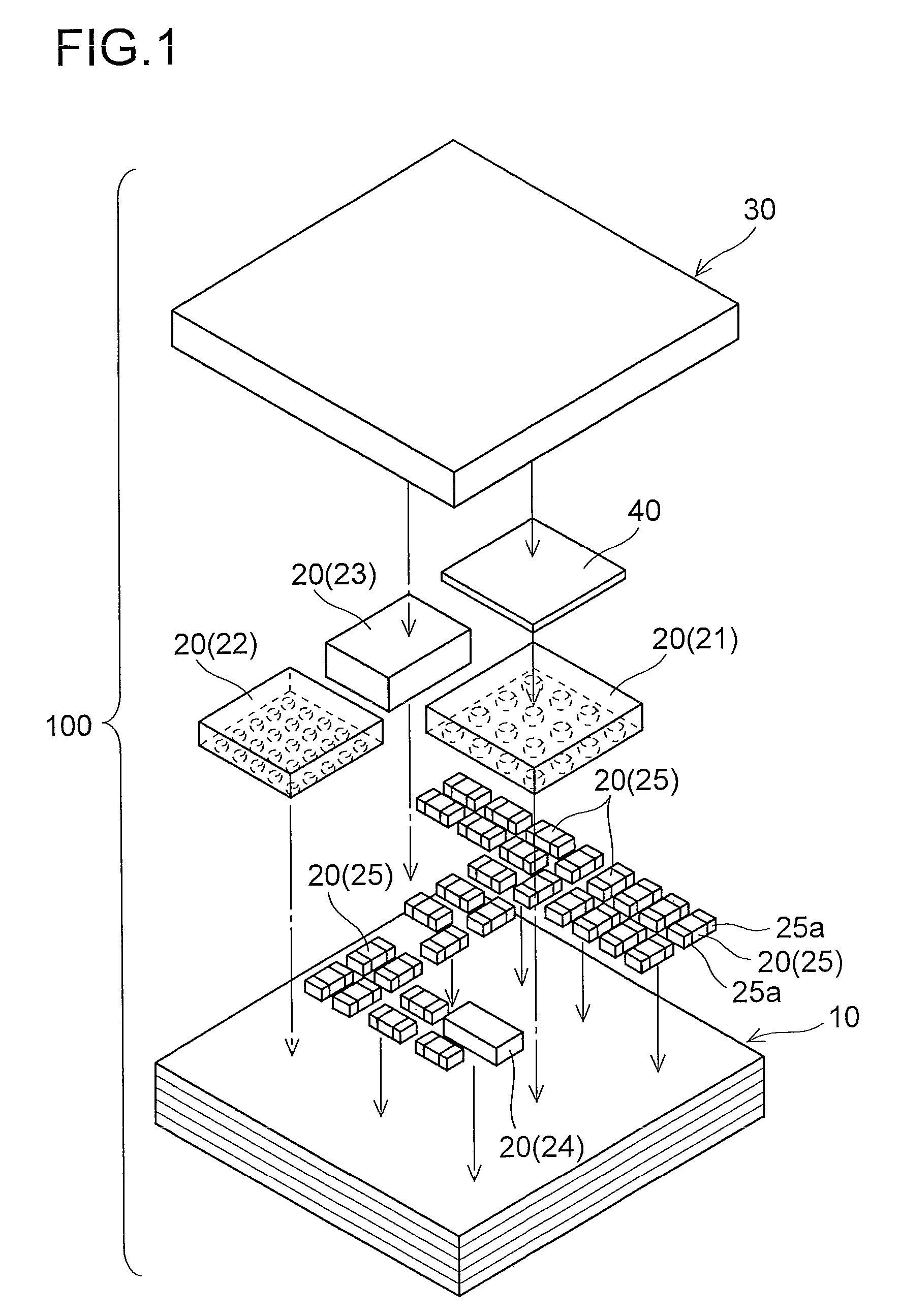
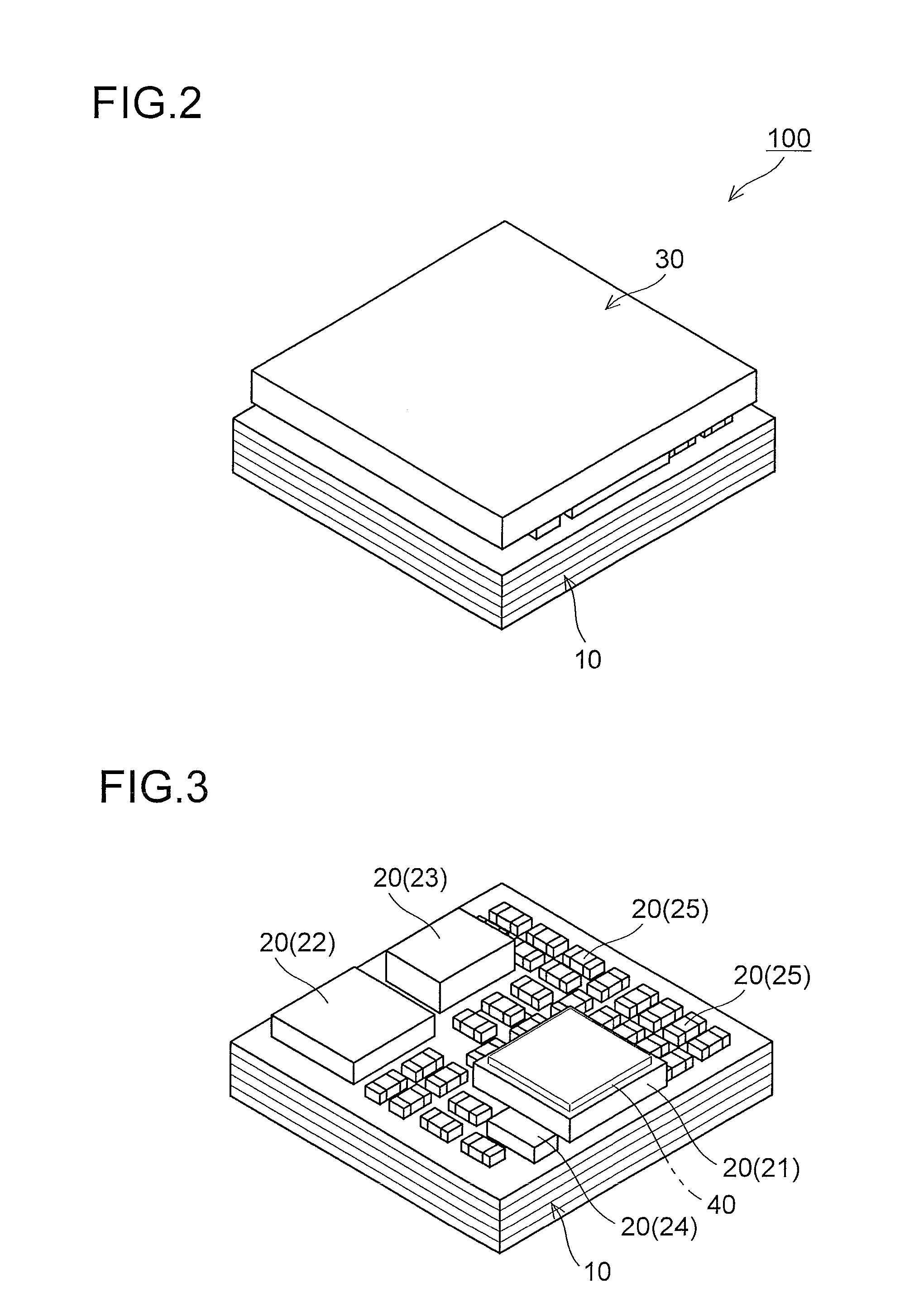
[0093]FIG. 1 is an exploded perspective view of an electronic component module according to a first embodiment of the present invention, and FIG. 2 is a general perspective view of the electronic component module according to the first embodiment of the present invention. FIG. 3 is a perspective view of the electronic component module according to the first embodiment of the present invention, and FIG. 4 is a plan view of the electronic component module according to the first embodiment of the present invention. FIGS. 5 to 10 are diagrams for illustrating a structure of the electronic component module according to the first embodiment of the present invention. Note that FIGS. 3 and 6 illustrate a state where a top plate is removed, and FIG. 5 illustrates a cross section cut along the line A-A in FIG. 4. First, with reference to FIGS. 1 to 10, the structure of an electronic component module 100 according to the first embodiment of the present invention will be...

second embodiment

[0150](Second Embodiment)

[0151]FIG. 31 is a cross sectional view of the electronic component module according to the second embodiment of the present invention. Next, with reference to FIGS. 5 and 31, a structure of the electronic component module 200 according to the second embodiment of the present invention will be described.

[0152]In the electronic component module 200 according to the second embodiment, unlike the first embodiment, the top plate is made of metal plate, and the top plate holding member is made of a curable resin material. In other words, in the second embodiment, as illustrated in FIG. 31, a top plate 230 made of metal plate is disposed instead of the top plate 30 constituted of the insulating plate (see FIG. 5). In addition, in the second embodiment, a top plate holding member 240 made of a curable resin material disposed instead of the top plate holding member 40 constituted of the metal plate (see FIG. 5).

[0153]The top plate 230 is made of metal plate such as ...

third embodiment

[0166](Third Embodiment)

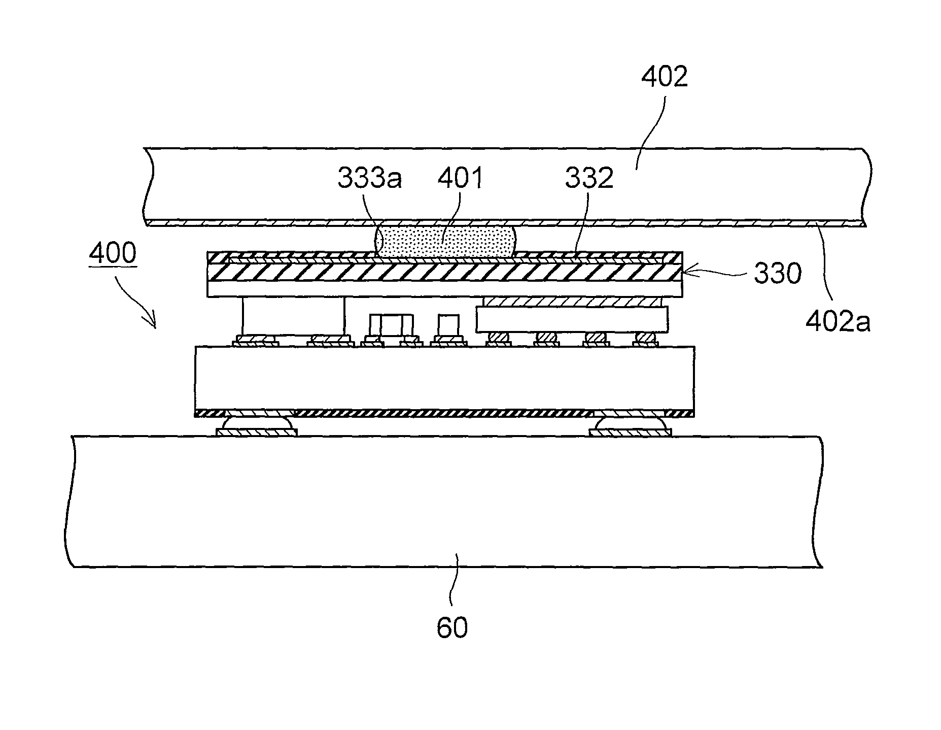
[0167]FIG. 34 is a cross sectional view of the electronic component module according to the third embodiment of the present invention. FIG. 35 is a plan view of the top plate of the electronic component module according to the third embodiment of the present invention. FIG. 36 is a cross sectional view cut along the line B-B in FIG. 35. Next, with reference to FIGS. 5 and 34 to 36, a structure of the electronic component module 300 according to the third embodiment of the present invention will be described.

[0168]This electronic component module 300 according to the third embodiment has a top plate 330 having a composite structure instead of the top plate 30 constituted of the insulating plate (see FIG. 5) in the structure of the first embodiment. Specifically, in the third embodiment, as illustrated in FIGS. 34 and 36, the top plate 330 has the composite structure (lamination structure) including a planar base material portion 331 having insulating property,...


PUM


Abstract

Provided is an electronic component module which has high reliability and is capable of suppressing reduction in handling performance of a mounting machine. An electronic component module includes a plurality of electronic components mounted on a top surface of a module substrate, a planar top plate covering the electronic components, and a top plate holding member for holding the top plate. The plurality of electronic components include a quartz resonator, and a RF-IC which has a height smaller than that of the quartz resonator and is disposed on the top surface of the module substrate so as to be side by side with the quartz resonator. In addition, the top plate is fixed to the quartz resonator, and the top plate holding member for holding the top plate is disposed between the RF-IC and the top plate.

Description

CROSS-REFERENCE TO RELATED APPLICATIONS[0001]This application is based on Japanese Patent Application No. 2009-102672 filed on Apr. 21, 2009, the contents of which are hereby incorporated by reference.BACKGROUND OF THE INVENTION[0002]1. Field of the Invention[0003]The present invention relates to an electronic component module.[0004]2. Description of Related Art[0005]In recent years, in the area of electronic equipment such as information communication equipment, demands for reduced size and increased performance of equipment has been growing. Therefore, downsizing, high performance and high density mounting of electronic components housed inside the equipment have been realized. In addition, the electronic components are designed as a module for higher performance and higher density mounting.[0006]An electronic component module containing a plurality of electronic components is mounted on a mounting substrate and housed inside the electronic equipment. In addition, the electronic c...

Claims


Application Information

Patent Timeline
Patent Type & Authority Patents(United States)
IPC IPC(8): H05K7/20
CPCH01L23/552H01L25/165H05K1/0243H05K9/006H05K1/181H05K2201/10371H05K2201/10522H01L2224/16227H01L2224/73253H01L2924/19105H01L2224/16225H01L2924/00014H01L2924/19107H01L2224/0401
Inventor YAMASHITA, MITSUYOSHIAMANO, YOSHIHISADEGUCHI, AKITERUKUSHINO, MASAHIKOMURAKAMI, MASAHIRO
Owner SHARP KK
Why Eureka
Try Eureka