
Steering tie rod end made of steel and method of manufacturing the same

a technology of steel and tie rod end, which is applied in the direction of manufacturing tools, heat treatment equipment, furniture, etc., can solve the problems of reducing the strength of each tie rod end, affecting the service life of the tie rod end, so as to achieve the effect of low strength and easy machin

Active Publication Date: 2012-05-29
TOYOTA JIDOSHA KK +1
View PDF18 Cites 4 Cited by
  • Summary
  • Abstract
  • Description
  • Claims
  • Application Information

AI Technical Summary

Benefits of technology

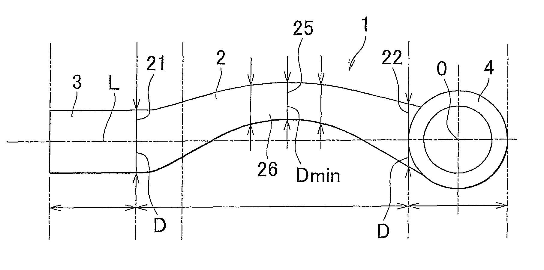
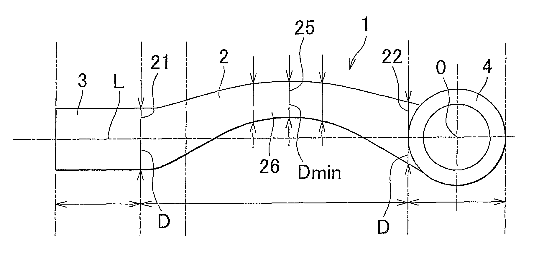
The invention provides a steel tie rod end with low rigidity, high strength, and excellent impact characteristic. The tie rod end has a minimum area portion with a small cross-sectional area, which allows for space saving and light weight. The minimum area portion has a high martensite fraction, which ensures necessary strength. The tie rod end has a high hardness in the minimum area portion, which improves its impact characteristic. The method of manufacturing the tie rod end involves forming a tie rod end intermediate with a prospective shaft portion, a prospective first fitting portion, and a prospective second fitting portion, applying high-frequency quenching to the prospective shaft portion, and then machining at least one of the first fitting portion and the second fitting portion.

Problems solved by technology

However, when the cross-sectional area of the shaft portion is just simply reduced, the strength of each tie rod end decreases.
This may possibly make it difficult to ensure necessary strength.
A tie rod end having a poor strength may possibly buckle or break.
However, generally, forming a tie rod end (particularly, forming fitting portions) requires machining, such as cutting.
Therefore, if the high strength material is used as the material of the tie rod end, machinability deteriorates.
This problematically increases cost for manufacturing the tie rod end.
Thus, if any of the tie rod ends breaks because of an impact in the event of a collision, or the like, steering function is impaired.

Method used


Image

  • Steering tie rod end made of steel and method of manufacturing the same
  • Steering tie rod end made of steel and method of manufacturing the same

Examples


Embodiment Construction

[0030]Hereinafter, a steel tie rod end and a method of manufacturing the steel tie rod end according to an embodiment of the invention will be described.

[0031]A steel tie rod end according to the embodiment of the invention includes a shaft portion; a first fitting portion that is continuous with a first end portion of the shaft portion in a longitudinal direction of the shaft portion; and a second fitting portion that is continuous with a second end portion of the shaft portion in the longitudinal direction of the shaft portion, wherein the shaft portion has a minimum area portion that is located between the first end portion and the second end portion, and a radially cross-sectional area of the minimum area portion is 80% or below of a radially cross-sectional area of the first end portion and 80% or below of a radially cross-sectional area of the second end portion, a martensite fraction of a steel structure of the minimum area portion is 90% or above, a surface hardness of the m...


PUM

PropertyMeasurementUnit
axial lengthaaaaaaaaaa
diameteraaaaaaaaaa
diameteraaaaaaaaaa

Abstract

A steel tie rod end includes a shaft portion and first and second fitting portions. A minimum area portion having a small radially cross-sectional area is provided for the shaft portion, and 90% or above of a steel structure of the minimum area portion is formed of martensite or tempered martensite. The surface hardness of the minimum area portion and the average hardness of the radial cross section of the minimum area portion are 600 Hv or below, and the average hardness of the radial cross section of the first fitting portion and the average hardness of the radial cross section of the second fitting portion are 300 Hv or below. A method of manufacturing a steel tie rod end includes a quenching process of heating only a prospective shaft portion by high frequency to an austenitizing temperature and then rapidly cooling the prospective shaft portion by water or cooling medium.

Description

BACKGROUND OF THE INVENTION[0001]1. Field of the Invention[0002]The invention relates to a steel tie rod end that constitutes part of a vehicle steering system and a method of manufacturing the steel tie rod end.[0003]2. Description of the Related Art[0004]Tie rods are components that constitute part of a vehicle steering system. The tie rods couple the steering system (for example, a steering gear of a rack and pinion steering system) to front wheel side components (for example, knuckle arms).[0005]Rotational motion of a steering wheel is transmitted to the steering system via a steering shaft. Then, the rotational motion is converted into linear motion by the steering system, and the linear motion is transmitted to front wheels via the tie rods and the knuckle arms. Each tie rod typically includes a tie rod body and a tie rod end. The tie rod body is assembled to the steering system via a ball joint. One end of the tie rod end is assembled to the tie rod body, and the other end of...

Claims


Application Information

Patent Timeline
Patent Type & Authority Patents(United States)
IPC IPC(8): B62D7/16
CPCB60G7/001B62D7/20C21D1/25C21D9/0068C21D9/0075B60G2206/11B60G2206/8401B60G2206/8402C21D2211/008C21D2221/01
Inventor KOMOTO, TAKESHISAKUMA, HITOSHIHIRANO, TAKASHIMIZUNO, HIROYUKITERAMOTO, SHINYATODA, MASAHIROTAKADA, HIROMASAOKONOGI, MAKOTO
Owner TOYOTA JIDOSHA KK
Learn More