
Reticle inspection systems and method

a technology of reticles and inspection systems, applied in the field of lithography, can solve problems such as defects in lithographic processes, adversely affecting the resulting product, and inability to use inspection systems,

Active Publication Date: 2012-05-29
ASML HLDG NV
View PDF11 Cites 8 Cited by
  • Summary
  • Abstract
  • Description
  • Claims
  • Application Information

AI Technical Summary

Benefits of technology

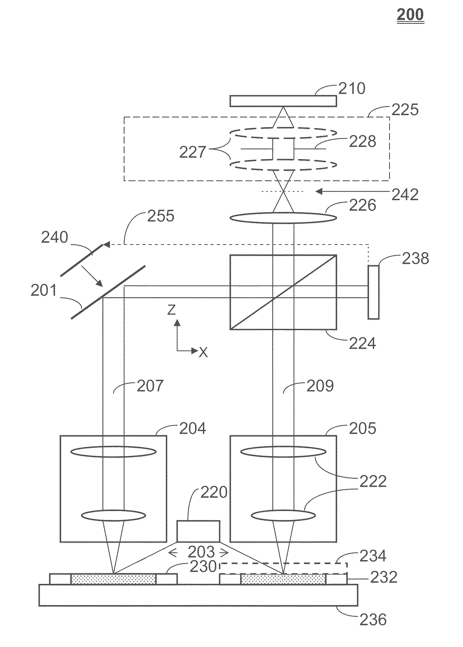
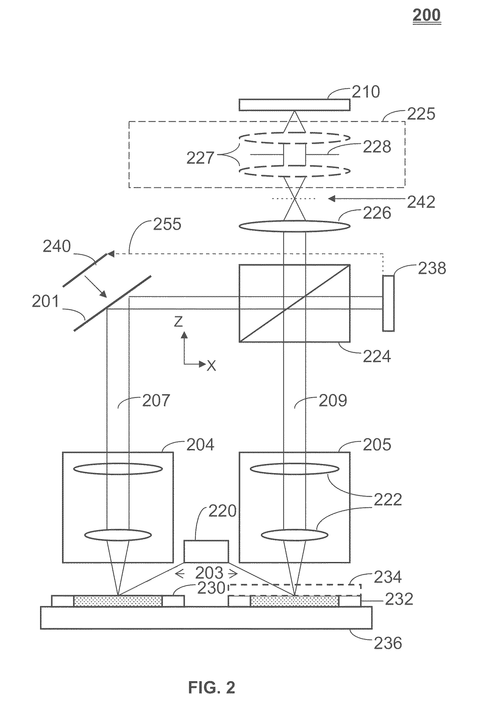
The present invention provides systems and methods for inspecting reticles with arbitrary patterns. The methods involve illuminating the reticle and a reference reticle with a coherent illumination source, applying a Fourier transform to scattered light from the illuminated portions, shifting the phase of the transformed light from the reference reticle to create an image representing a difference in amplitude and phase distributions of the reticle and the reference reticle, detecting the combined light, and using an interferometer element to induce a 180-degree phase shift. The systems include a coherent illumination source, inspection interferometer branch, interferometer element, and detector. The invention allows for easy detection of foreign particles and defects on reticles, which is useful in the manufacturing process of semiconductor devices.

Problems solved by technology

Dust or extraneous particulate matter appearing on the surface of the reticle can adversely affect the resulting product.
Because the EUV reticles are not covered, they are prone to particle contamination, which may cause defects in a lithographic process.
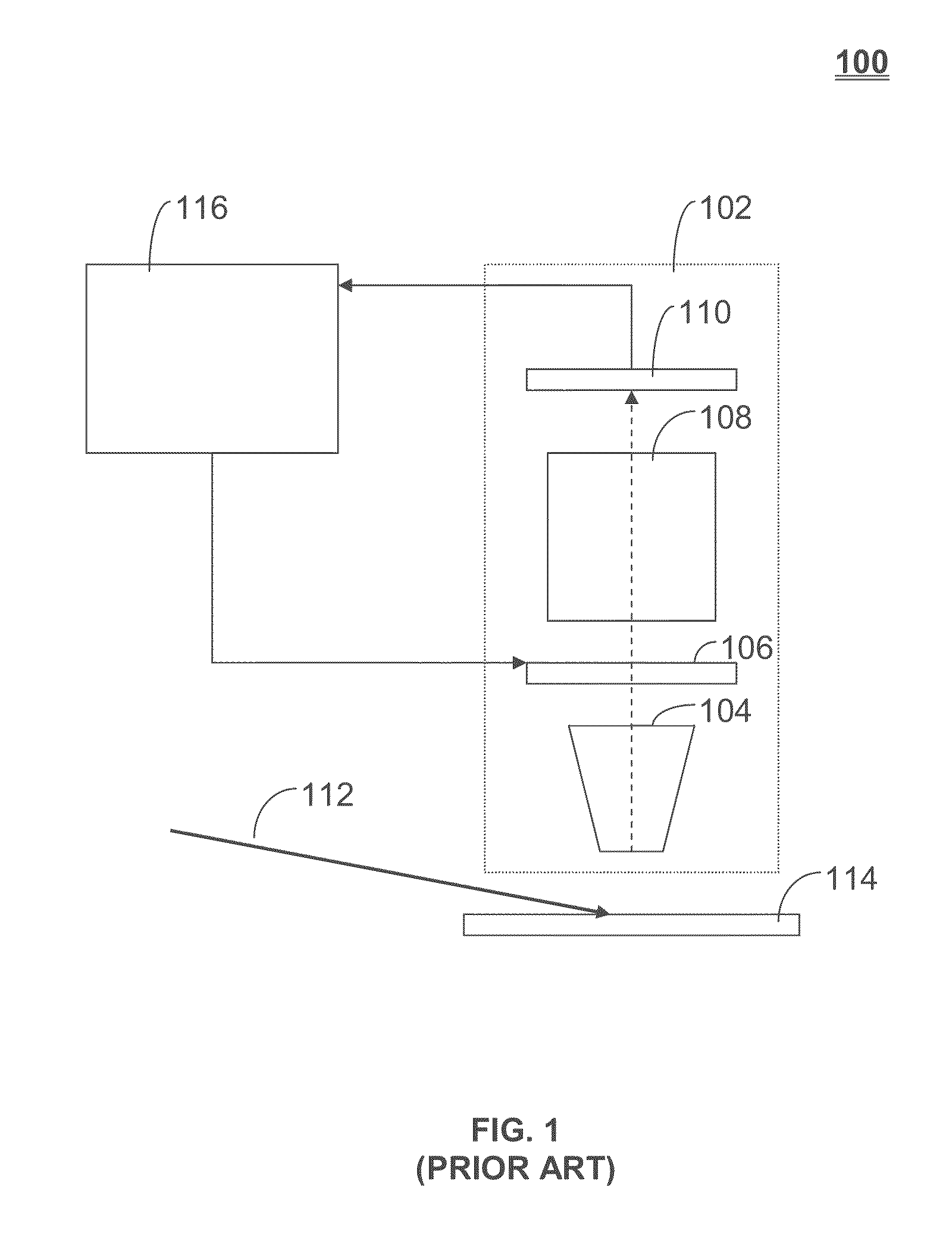
It is not feasible, however, to use an inspection system such as inspection system 100 on reticles having arbitrary (i.e., non-periodic) patterns.
This limitation is a result of saturation of the detector by light diffracted by the pattern.
The detector has limited dynamic range and cannot detect light from a particle in the presence of light scattered from the pattern.
Even with a periodic pattern (e.g., for DRAM), there are significant issues when modifying a Fourier filter in a reticle scanning process.
With an inspection system such as inspection system 100, there is also a limitation to use only a collimated illumination beam for its Fourier filtration.
Therefore, it does not allow the illumination optimization necessary for suppression of scattering from reticle surface roughness.
Precision, quality, and certainty of particle detection is very often compromised when using known inspection systems.

Method used


Image

  • Reticle inspection systems and method
  • Reticle inspection systems and method
  • Reticle inspection systems and method

Examples


Embodiment Construction

I. Overview

[0035]The present invention is directed to reticle inspection systems and methods. This specification discloses one or more embodiments that incorporate the features of this invention. The disclosed embodiment(s) merely exemplify the invention. The scope of the invention is not limited to the disclosed embodiment(s). The invention is defined by the claims appended hereto.

[0036]The embodiment(s) described, and references in the specification to “one embodiment”, “an embodiment”, “an example embodiment”, etc., indicate that the embodiment(s) described may include a particular feature, structure, or characteristic, but every embodiment may not necessarily include the particular feature, structure, or characteristic. Moreover, such phrases are not necessarily referring to the same embodiment. Further, when a particular feature, structure, or characteristic is described in connection with an embodiment, it is understood that it is within the knowledge of one skilled in the art...


PUM


Abstract

A method and systems for reticle inspection. The method includes coherently illuminating surfaces of an inspection reticle and a reference reticle, applying a Fourier transform to scattered light from the illuminated surfaces, shifting the phase of the transformed light from the reference reticle such that a phase difference between the transformed light from the inspection reticle and the transformed light from the reference reticle is 180 degrees, combining the transformed light as an image subtraction, applying an inverse Fourier transform to the combined light, and detecting the combined light at a detector. An optical path length difference between two optical paths from the illumination source to the detector is less than a coherence length of the illumination source. The image detected by the detector represents a difference in amplitude and phase distributions of the reticles allowing foreign particles, defects, or the like, to be easily distinguished.

Description

CROSS REFERENCE TO RELATED APPLICATION(S)[0001]This application claims benefit under 35 U.S.C. §119(e) to U.S. Provisional Patent Application No. 61 / 122,488, filed Dec. 15, 2008, which is incorporated by reference in its entirety.BACKGROUND[0002]1. Field of the Invention[0003]The present invention generally relates to lithography, and more particularly to inspection of reticles used for lithography.[0004]2. Background Art[0005]Lithography is widely recognized as a key process in manufacturing integrated circuits (ICs) as well as other devices and / or structures. A lithographic apparatus is a machine, used during lithography, which applies a desired pattern onto a substrate, such as onto a target portion of the substrate. During manufacture of ICs with a lithographic apparatus, a patterning device (which is alternatively referred to as a mask or a reticle) generates a circuit pattern to be formed on an individual layer in an IC. This pattern may be transferred onto the target portion ...

Claims


Application Information

Patent Timeline
Patent Type & Authority Patents(United States)
IPC IPC(8): G01B11/02
CPCG01N21/95607G03F1/84G03F7/70525G03F7/70916G03F7/70975G03F7/70991G01B9/02022G01B9/02068G01N2021/95676G03F7/2057
Inventor SHMAREV, YEVGENIY KONSTANTINOVICHCATEY, ERIC BRIANTHARALDSEN, ROBERT ALBERTJACOBS, RICHARD DAVID
Owner ASML HLDG NV
Learn More