Systems and methods for characterizing spatial distortion in 3D imaging systems

a technology of 3d imaging and spatial distortion, applied in the field of image guided therapy, can solve the problems of compromising the efficacy of intended therapy, compromising the ability to accurately deliver appropriate therapy, and all known imaging technologies suffering from some degree of spatial distortion, and achieve the effect of reducing spatial distortion

Inactive Publication Date: 2012-05-29
LOMA LINDA UNIV MEDICAL CENT
View PDF129 Cites 59 Cited by
  • Summary
  • Abstract
  • Description
  • Claims
  • Application Information

AI Technical Summary

Benefits of technology

[0015]Embodiments further include operating on the second measured spatial locations so as to create a corrected set of measured spatial locations having reduced spatial distortion with respect to the first known spatial locations.
[0020]Embodiments further include wherein the analysis module further operates on the second measured spatial locations so as to create a corrected set of measured spatial locations having reduced spatial distortion with respect to the first known spatial locations.

Problems solved by technology

Errors in accurately identifying the spatial location of a desired target region can compromise the ability to accurately deliver the appropriate therapy.
This can at best compromise the efficacy of the intended therapy by misdirecting the therapy and in some applications can have safety concerns, for example by unintentionally delivering the therapy to non-target regions.
A variety of imaging technologies can be used in IGT, however all known imaging technologies suffer from some degree of spatial distortion.
However, location data obtained via MRI systems is subject to spatial distortion from magnetic field distortions as well as chemical shifts that may occur within the imaging volume.
However, CT imaging is also subject to distortion from a phenomenon known as beam hardening.
SPECT and PET systems are subject to spatial distortion from such factors as attenuation and / or scatter of the gamma rays or gamma photons.

Method used


Image

  • Systems and methods for characterizing spatial distortion in 3D imaging systems
  • Systems and methods for characterizing spatial distortion in 3D imaging systems
  • Systems and methods for characterizing spatial distortion in 3D imaging systems

Examples


Embodiment Construction

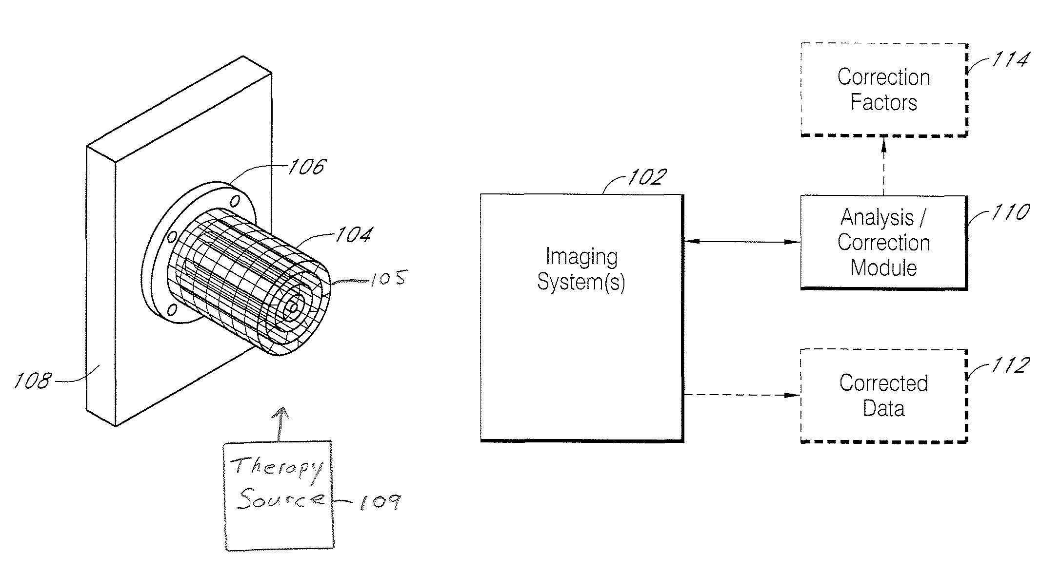
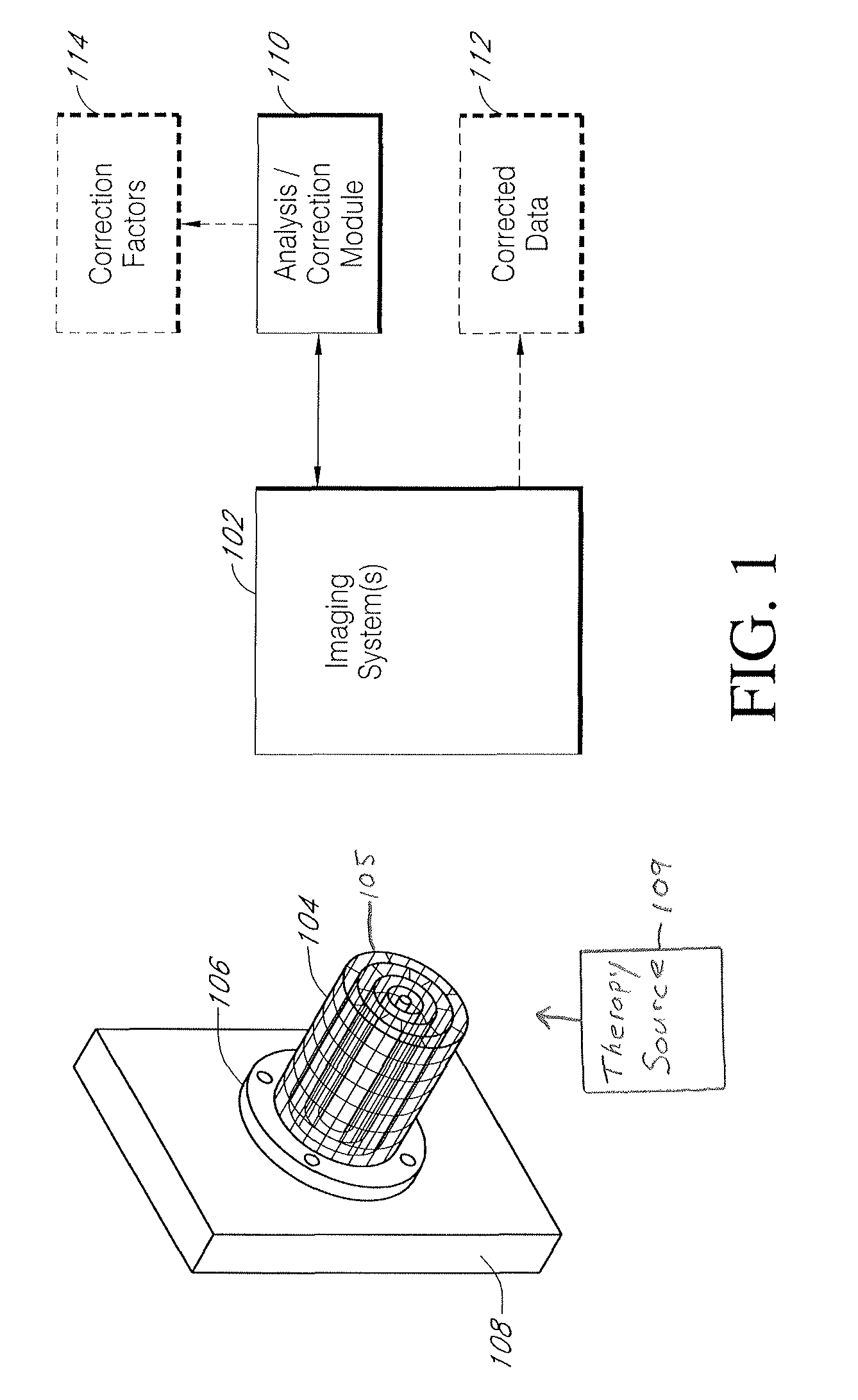
[0036]FIG. 1 illustrates schematically embodiments of a system for characterizing spatial distortions that may occur in image data obtained by an imaging system 102. The imaging system 102 can comprise one or more of a wide variety of imaging technologies including but not limited to MRI, CT, SPECT, and PET. The imaging system 102 can passively monitor one or more types of emissions from an imaging volume or space. The imaging systems 102 may also generate or project fields, energies, and / or particles and monitor interactions of these projected or generated energies and / or particles with the imaged volume.

[0037]As previously noted, known imaging systems 102 are subject to at least some degree of spatial distortion. In at least some applications, the spatial distortion is at least in part generally repeatable and can be referred to as machine dependent distortion. Such distortion is generally dependent on the design and construction of a given imaging system 102 and the nature of the...


PUM


Abstract

Systems and methods for characterizing spatial distortions in location data determined by an imaging system, for example as employed in imaged guided therapy. A three dimensional phantom is custom formed for a desired imaging space of a given imaging system. The phantom includes a large plurality of control points fixed rigidly in space to a high degree of known accuracy. The phantom is fixed to a stereotactic frame defining a known calibrated reference or zero and imaged. An algorithm customized for the phantom determines the spatial locations of the control points. A comparison is made between the known and the determined spatial locations for at least a subset of the control points. The comparison results in indicia for any determined spatial distortions observed. The raw image data can be manipulated to compensate for any spatial distortion. The control points can have fixed locations known to an accuracy of 100μ or better. The algorithm can determine an initial estimate for the detected location of a control point accurate to ±0.5 pixel or better.

Description

CROSS-REFERENCE TO RELATED APPLICATIONS[0001]This application claims the benefits of U.S. Provisional Application 61 / 030,914 filed Feb. 22, 2008.BACKGROUND OF THE INVENTION[0002]1. Field of the Invention[0003]The invention relates to the field of image guided therapy and to systems and methods for creating and utilizing phantoms for characterizing imaging errors to facilitate correction of such errors.[0004]2. Description of the Related Art[0005]Image Guided Therapies (IGT) refers to a wide range of existing and developing treatment modalities that employ one or more imaging technologies to assist more effective delivery of the related therapy. IGT can include but is not limited to such treatment modalities as image guided surgery, radiosurgery, radiotherapy, and other existing and developing types of therapy. In general, IGT utilizes one or more imaging technologies to gather information indicative of the internal structures and / or condition of tissue of interest. Image data is obt...

Claims


Application Information

Patent Timeline
Patent Type & Authority Patents(United States)
IPC IPC(8): G06K9/00A61B5/05
CPCA61B6/037A61B6/583A61B19/52G06T15/08A61N5/1049G06T7/0016A61B5/055A61B2017/00716A61B2017/00725A61N2005/1061G06T2207/10072A61N2005/1052A61N2005/1055G01R33/58A61B90/36A61N2005/1076B33Y80/00B33Y50/00G06T5/20G06T11/003G06T2200/04G06T2207/10012
Inventor PEARLSTEIN, ROBERT D.KITTLE, DAVID SCOTTHOLSHOUSER, BARBARA ANN
Owner LOMA LINDA UNIV MEDICAL CENT
Why Eureka
Try Eureka