Mixing apparatus and method for manufacturing an emulsified fuel

a technology of emulsified fuel and mixing device, which is applied in the direction of mechanical equipment, fuels, transportation and packaging, etc., can solve the problems of inability to meet the needs of aqueous fuel emulsion production, etc., to achieve the effect of inexpensive mixing devi

Active Publication Date: 2012-06-05
TALISMAN CAPITAL TALON FUND
View PDF37 Cites 8 Cited by
  • Summary
  • Abstract
  • Description
  • Claims
  • Application Information

AI Technical Summary

Benefits of technology

[0043]The present invention addresses the aforementioned problems by incorporating a specially designed mixing unit into a blending system and method for producing aqueous fuel emulsions with consistently uniform dispersed phase particle sizes with a relatively inexpensive mixing device. Specifically, the present invention relates to a specially designed mixing devic...

Problems solved by technology

As is well known in the art, the constituent parts of such aqueous fuel emulsions have a tendency to separate or be unstable over time because of the different densities or relative weights of the primary components, as well as other factors including the immiscibility of the compounds.
Any breakdown in the aqueous fuel emulsion can be extremely damaging if not detected before use in combustion.
Given the microscopic nature of the suspended particles with the discontinuous phase, aqueous fuel emulsions can look acceptable to the naked eye but can actually be considered unacceptable when subjected to quality control standards to one skilled in the art.
However, these additional high shear mixing devices or loope...

Method used


Image

  • Mixing apparatus and method for manufacturing an emulsified fuel
  • Mixing apparatus and method for manufacturing an emulsified fuel
  • Mixing apparatus and method for manufacturing an emulsified fuel

Examples


example 1

[0078]In this example, the Rotor Stator Mixer used is a Silverson™ model 150 L with a fine mesh screen (having a hole size of about 0.02″) powered by a 60 HZ motor at about 100%. The individual ingredients and aqueous fuel emulsion were subjected to recirculation within the rotor stator mixing five times. At the end of each pass, a sample was taken for measurement.

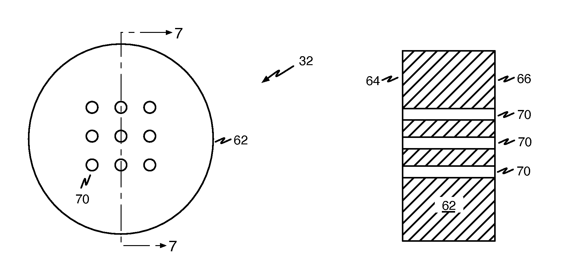
[0079]The mixer used is illustrated in FIG. 5. The individual ingredients and aqueous fuel emulsion was moved at a rate of 1 gpm and the height of the gap was about 0.03 in. The individual ingredients of the aqueous fuel emulsion were subjected to the specifically designed mixer mixing one time. A sample from the first pass was taken for measurement.

[0080]The aqueous fuel emulsion was prepared under the general method described previously with the constituents also described. The particle sizes of the discontinuous phase (or the water) were measured by an accoustizer. Referring to Tables 1 and 2, the accoustizer provided m...


PUM

PropertyMeasurementUnit
Flow rateaaaaaaaaaa
Particle sizeaaaaaaaaaa

Abstract

A mixing apparatus is disclosed. The mixing apparatus comprises a mixing device having a constant flow area. The mixing device is configured to create a shearing environment. Several types of mixing apparatus are disclosed. Methods for producing aqueous fuel emulsions with consistently uniform dispersed phase particle sizes using a mixing apparatus are also disclosed.

Description

CROSS-REFERENCE TO RELATED APPLICATIONS[0001]This application is a divisional of co-pending U.S. patent application Ser. No. 11 / 853,548, filed Sep. 11, 2007, which is a divisional of U.S. patent application Ser. No. 10 / 754,885, filed Jan. 9, 2004, now abandoned, the entirety of both are incorporated by reference herein.BACKGROUND[0002]The present invention relates to a mixing device for manufacturing an aqueous fuel, and more particularly to a specially designed mixing device that creates a superior aqueous fuel emulsion from a hydrocarbon fuel, water, and an aqueous fuel emulsifier package.[0003]Recent fuel developments have resulted in a number of aqueous fuel emulsions comprised essentially of a carbon-based fuel, water, and various additives, such as lubricants, emulsifiers, surfactants, corrosion inhibitors, cetane improvers, and the like. These aqueous fuel emulsions may play a key role in finding a cost-effective way for internal combustion engines including, but not limited ...

Claims


Application Information

Patent Timeline
IPC IPC(8): B01F5/06C10L1/32B01F25/46
CPCB01F3/0807B01F5/0665B01F5/0681B01F5/0682B01F5/0689C10L1/328B01F23/41B01F25/4413B01F25/4423B01F25/45211B01F25/45
Inventor WALDRON, JACK L.GRIMES, PATRICK
Owner TALISMAN CAPITAL TALON FUND
Why Eureka
Try Eureka