Controller and method for controlling an intensity of a light emitting diode (LED) using a conventional AC dimmer

a technology of light emitting diodes and controllers, applied in the direction of electric variable regulation, process and machine control, instruments, etc., can solve the problems of flicker, high frequency harmonics, and the power of leds using dc typical converters,

Active Publication Date: 2012-06-05
SAVANT TECH LLC
View PDF16 Cites 20 Cited by
  • Summary
  • Abstract
  • Description
  • Claims
  • Application Information

AI Technical Summary

Problems solved by technology

However, there are several technical reasons which militate against this.
One problem is that LEDs are powered using DC typical converters and are not ideally suited to operation from an AC supply particularly when operated at reduced output.
Specifically, when power is reduced such that there is insufficient load on the triac, this gives rise to flicker.
This is unpleasant when dimmers are used with low power halogen lamps that may have a power rating of 20 W, but it can be quite intolerable when used with LEDs having a power rating of only 1 W.
The voltage that is applied to the lamp is the low frequency envelope that contains high frequency harmonics, which are undesirable when using LEDs.
This also is unsuitable for use with LEDs, which require a stabilized voltage source.
This may also militate against the use of conventional AC dimmers.
As a result, when the dimmer is set too low, there is the risk that there will be insufficient voltage to power the controller.
This creates a dead space of the dimmer, where the controller is shut down and the LEDs are consequently extinguished.
It does not provide a circuit for varying the intensity of an LED over substantially the full range of an AC dimmer.
It is apparent that the limitations of WO 03 / 096761 derive from operating the power control circuitry directly from the AC dimmer output.

Method used


Image

  • Controller and method for controlling an intensity of a light emitting diode (LED) using a conventional AC dimmer
  • Controller and method for controlling an intensity of a light emitting diode (LED) using a conventional AC dimmer
  • Controller and method for controlling an intensity of a light emitting diode (LED) using a conventional AC dimmer

Examples


Embodiment Construction

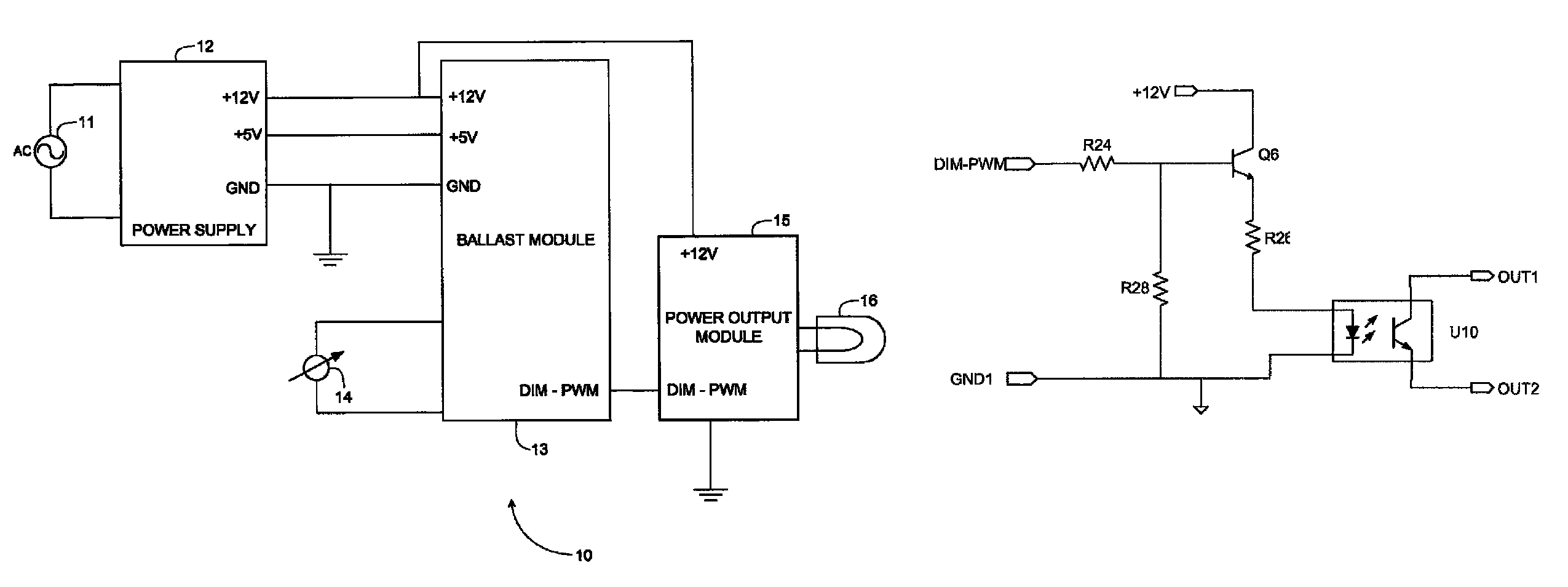
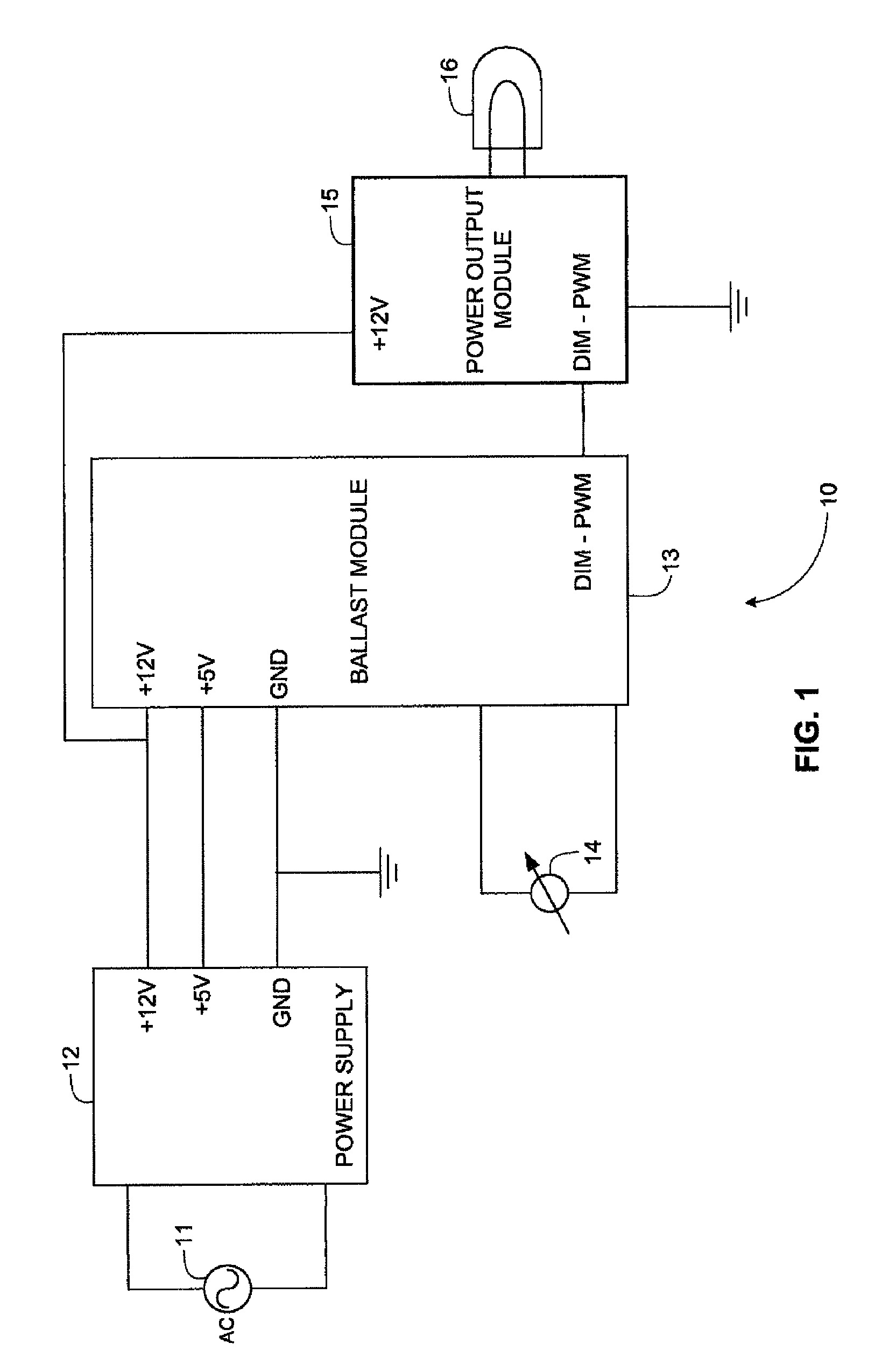
[0033]FIG. 1 is a block circuit diagram showing functionally a LED dimmer circuit 10 according to an embodiment of the invention. An AC main supply 11 is fed to a power supply 12 that has +5 and +12 volt outputs fed to corresponding inputs of a ballast module 13. The ballast module 13 constitutes a control circuit that has control inputs coupled to a conventional AC lamp dimmer 14 and includes a pulse width modulation circuit having an output shown as DIM-PWM that varies according to the firing angle of the dimmer 14. The output DIM-PWM of the ballast module 13 is coupled to a power output module 15 that is powered by the +12 V output of the power supply 12 and that has an output to which one or more LEDs 16 are coupled.

[0034]It will thus be noted that in the circuit shown in FIG. 1, the AC dimmer 14 serves only to feed a signal indicative of its firing angle to the ballast module 13. The power supply 12 is fed directly from the AC mains supply 11, which may be a universal power sup...


PUM


Abstract

A flicker-free method and a control circuit is used in conjunction with a conventional AC dimmer coupled to a main-AC supply to continuously control an intensity of a Light Emitting Diode (LED) over substantially a full range of the dimmer. The control circuit has a controllable source of DC voltage that is configured for coupling to at least one LED and that is powered independently of an output of the AC dimmer thereby isolating the LED voltage from the output of the AC dimmer; and a controller coupled to the source of DC voltage. The controller is powered independently of the output of the AC dimmer and is responsive to a firing angle of the AC dimmer for varying a level of the DC voltage as a function of said firing angle.

Description

CROSS REFERENCE TO RELATED APPLICATIONS[0001]This application claims the benefit of Israeli Patent Application Number 188348 filed on Dec. 24, 2007 which is hereby incorporated by reference herein.FIELD OF THE INVENTION[0002]This invention relates to dimmers for use with Light Emitting Diodes (LEDs).BACKGROUND OF THE INVENTION[0003]Lamp dimmers for coupling to the AC mains supply voltage typically employ angle modulation of a switching device such as a triac so as to adjust the duty cycle of the AC dimmer output signal. In so-called “leading edge” dimmers, the triac is selectively operated to adjust the duty cycle (i.e. modulate the phase angle) of the dimmer output signal by removing rising portions of AC voltage half-cycles (i.e. after zero-crossings and before peaks). In so-called “trailing edge” a triac can be controlled to remove falling portions of AC voltage half-cycles (i.e. after peaks and before zero-crossings).[0004]With the growing popularity of LEDs for domestic and oth...

Claims


Application Information

Patent Timeline
Patent Type & Authority Patents(United States)
IPC IPC(8): H05B37/02H05B44/00
CPCH05B33/0851H05B45/59H05B45/10
Inventor LEIDERMAN, SLAVA
Owner SAVANT TECH LLC
Why Eureka
Try Eureka