
Method for transmitting data in multiple antenna system

a data transmission and antenna technology, applied in the field of wireless communication, can solve the problems of increasing the overhead of feedback data, difficulty in designing the codebook, etc., and achieve the effect of reducing the complexity of the system and ensuring backward compatibility for user equipmen

Active Publication Date: 2012-06-05
LG ELECTRONICS INC
View PDF27 Cites 42 Cited by
  • Summary
  • Abstract
  • Description
  • Claims
  • Application Information

AI Technical Summary

Benefits of technology

The present invention provides a method for efficiently applying a codebook-based precoding scheme to multiple increased antennas in a wireless communication system. This method reduces the complexity of the system and ensures backward compatibility for user equipment not supporting multiple increased antennas. The invention also includes a method for estimating the transmission antenna channels of a Base Station and receiving precoded and transmitted data using the feedback precoding matrix or a precoding weight induced from the estimated channels. The technical effects of the invention include improved data transfer rate, increased system capacity, and reduced overhead of feedback data.

Problems solved by technology

If the number of codebook sets increases according to the increased number of antennas, not only the overhead of feedback data may be increased, but also there is a difficulty in designing the codebook.

Method used


Image

  • Method for transmitting data in multiple antenna system
  • Method for transmitting data in multiple antenna system
  • Method for transmitting data in multiple antenna system

Examples


Embodiment Construction

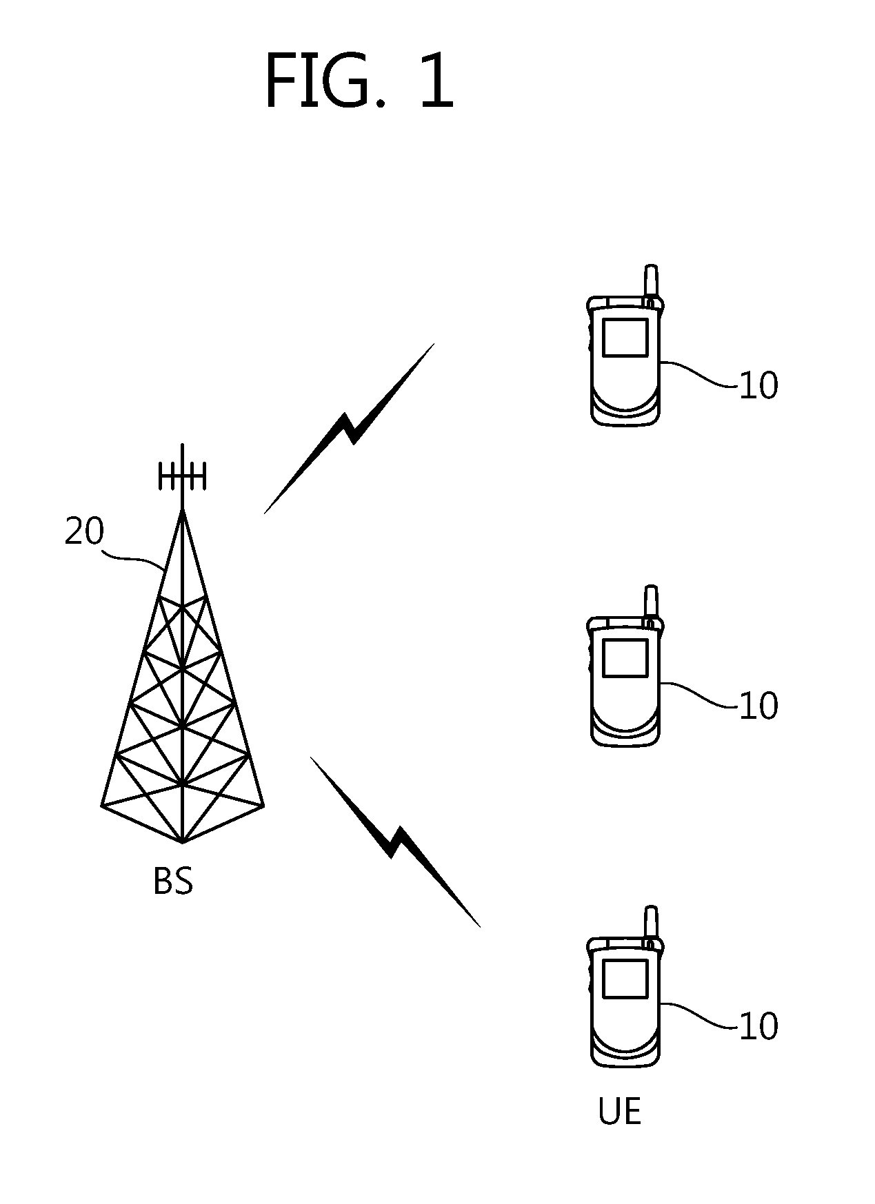
[0016]FIG. 1 is a block diagram showing a wireless communication system. The wireless communication systems are widely deployed in order to provide various communication services, such as voice and packet data.

[0017]Referring to FIG. 1, the wireless communication system includes User Equipment (UE) 10 and a Base Station (BS) 20. The UE 10 may be fixed or mobile and called another terminology, such as a Mobile Station (MS), a User Terminal (UT), a Subscriber Station (SS), or a wireless device. In general, the BS 20 refers to a fixed station communicating with the UEs 10, and it may be called another terminology, such as a Node-B, a Base Transceiver System (BTS), or an access point. One or more cells may exist in one BS 20.

[0018]Hereinafter, downlink (DL) refers to communication from the BS 20 to the UE 10, and uplink (UL) refers to communication from the UE 10 to the BS 20. In downlink, a transmitter may be part of the BS 20, and a receiver may be part of the UE 10. In uplink, a tran...


PUM


Abstract

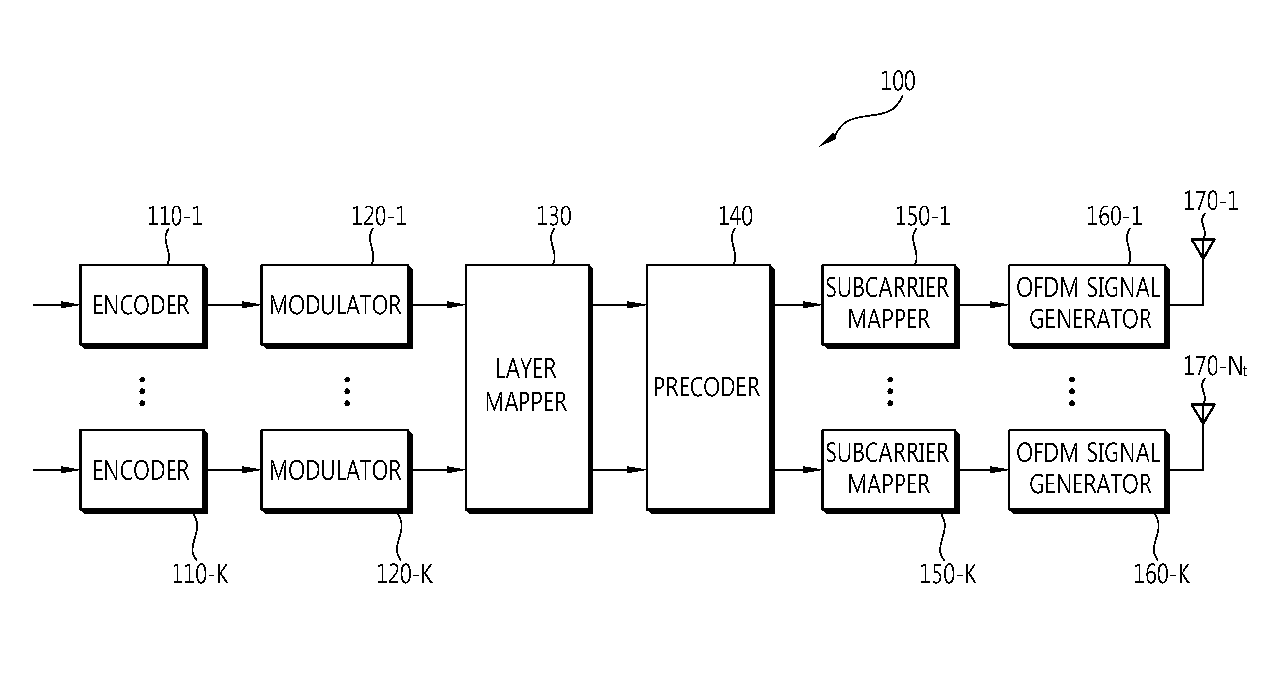
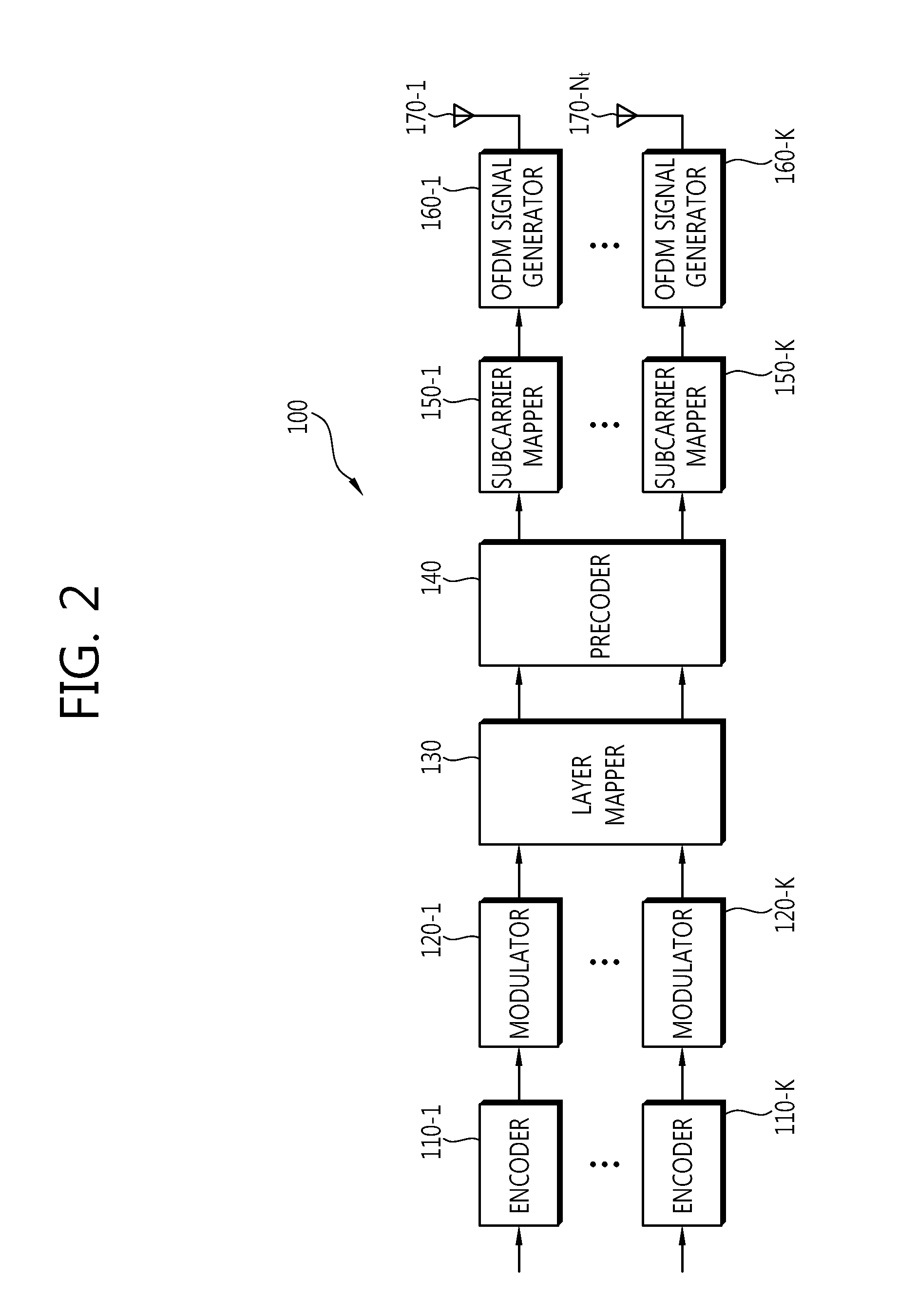
A method of sending data in a multiple antenna system includes the steps of generating a transmission signal by applying channel-dependent precoding to a first antenna cluster and a second antenna cluster, each comprising a plurality of antennas, wherein the channel-dependent precoding is performed by a precoding weight matrix in which a precoding weight for each of the antenna clusters has a block diagonal form and the precoding weight is represented by P×V for a number of transmission antennas P, included in each of the antenna clusters, and a number of layers V applied to each of the antenna clusters (P and V are an integer greater than 0) and sending the transmission signal.

Description

CROSS-REFERENCE TO RELATED APPLICATIONS[0001]This application is a 371 U.S. national stage application of International Application No. PCT / KR2009 / 004235, filed on Jul. 29, 2009, which claims priority to Korean Application No. 10-2009-0042773, filed on May 15, 2009, and U.S. Provisional Application Serial Nos. 61 / 154,424, filed on Feb. 22, 2009, and 61 / 084,622, filed on Jul. 30, 2008, the contents of which are incorporated by reference herein in their entirety.TECHNICAL FIELD[0002]The present invention relates to wireless communication, and more specifically to a method of sending data using multiple antennas.BACKGROUND ART[0003]A Multiple-Input Multiple-Output (MIMO) has recently been in the spotlight in order to maximize the performance and communication capacity of a wireless communication system. MIMO technology is a method which breaks away from technology using one transmission antenna and one reception antenna and can improve the transmission efficiency of transmission / recept...

Claims


Application Information

Patent Timeline
Patent Type & Authority Patents(United States)
IPC IPC(8): H04B7/02
CPCH04B7/0413H04B7/06
Inventor KO, HYUN SOOCHUN, JIN YOUNGLEE, MOON ILIHM, BIN CHULLEE, WOOK BONG
Owner LG ELECTRONICS INC
Learn More