Floating underwater support structure

a support structure and underwater technology, applied in the direction of marine propulsion, vessel construction, special-purpose vessels, etc., can solve the problems of tlps not being tlps are not ideal for supporting lighter structures, and the other solutions for supporting lighter structures in shallow and moderately deep water are relatively few

Active Publication Date: 2012-06-12
CLEAR PATH ENERGY
View PDF49 Cites 33 Cited by
  • Summary
  • Abstract
  • Description
  • Claims
  • Application Information

AI Technical Summary

Problems solved by technology

However, if a TLP is placed in shallow water, it is more affected by wave loads, which could introduce compression into the tension legs and risk capsizing the TLP.
Thus, TLPs are not ideal for supporting lighter structures, such as wind turbines, that are to be placed closer to shore in shallow or moderately deep water.
Unfortunately, other solutions for supporting lighter structures in shallow and moderately deep water are relatively few.
Moreover, support structures that work well in shallow water are often hard to implement in deeper water, and as with TLPs, support structures intended for deeper water often do not work well in shallow water.
However, that approach often results in a structure that is large and heavy.
Another approach is to build a platform or support with rigid legs that reach all the way to the sea floor, but that approach may only be feasible in relatively shallow water.
Ultimately, the lack of good solutions for supporting floating structures has resulted in structures like wind turbines being placed primarily in shallow water (e.g., 35 m or less).
There are a limited number of economically and technically feasible choices for supporting wind turbines and other structures in water that is, for example, 35-200 m deep, yet there are many otherwise suitable sites with water depths in that range.

Method used


Image

  • Floating underwater support structure
  • Floating underwater support structure
  • Floating underwater support structure

Examples


Embodiment Construction

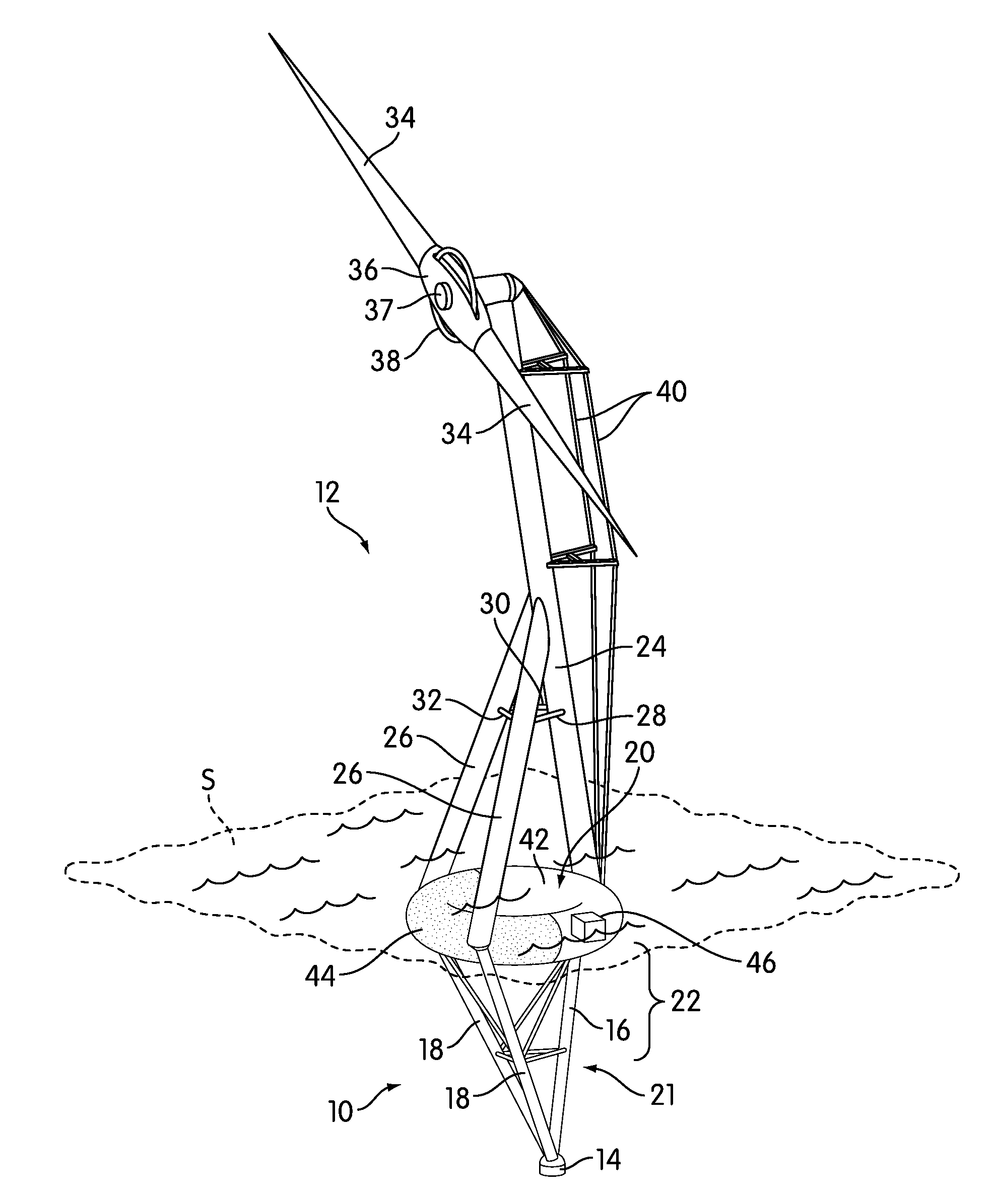
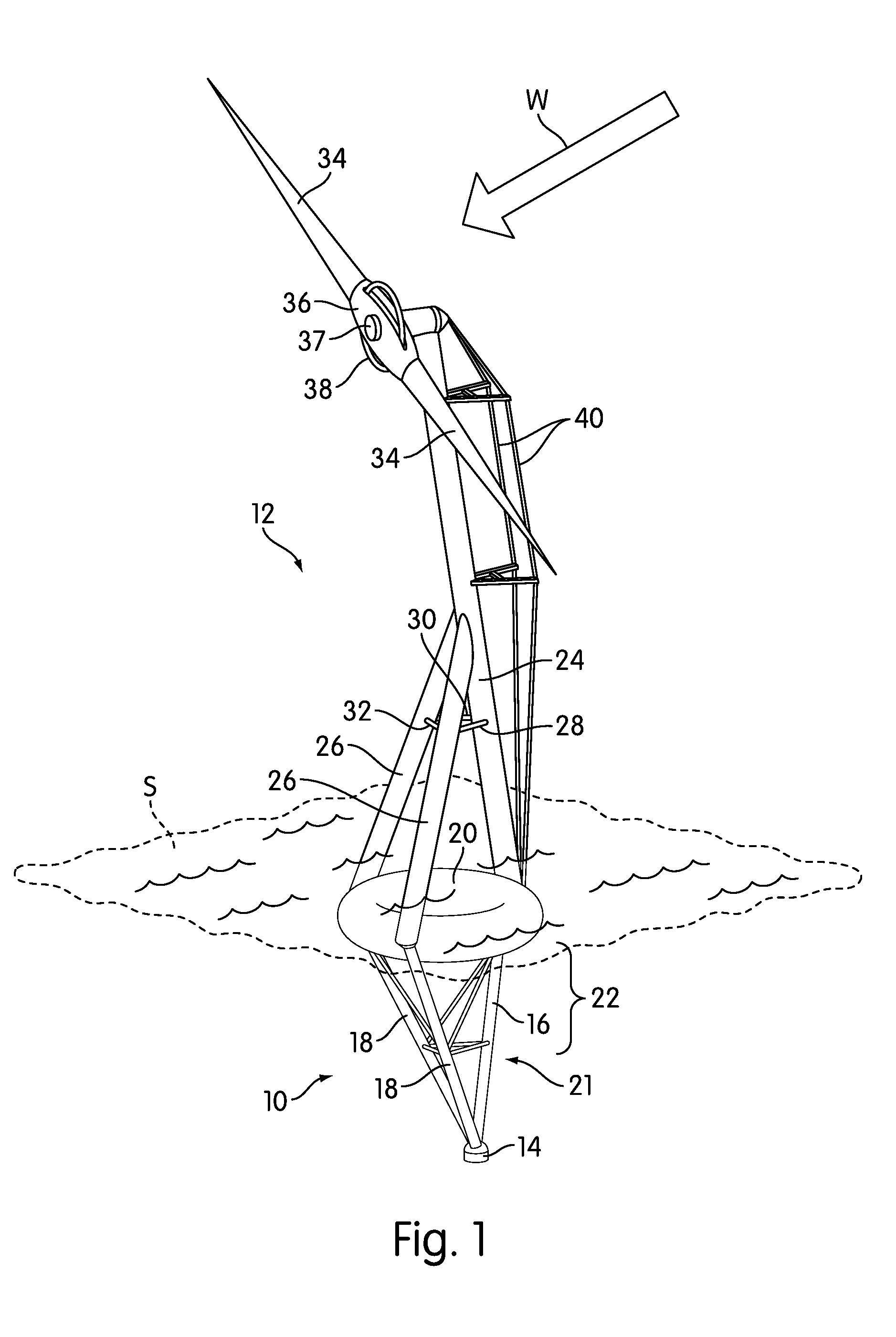
[0023]FIG. 1 is a perspective view of a floating underwater support structure, generally indicated at 10, according to one embodiment of the invention. In the view of FIG. 1, the floating underwater support structure 10 is shown supporting a wind turbine 12. In the following description, certain aspects and advantages of the floating underwater support structure 10 will be described with respect to its use with wind turbines, although as will be described below, the floating underwater support structure 10 may be used to support a variety of structures.

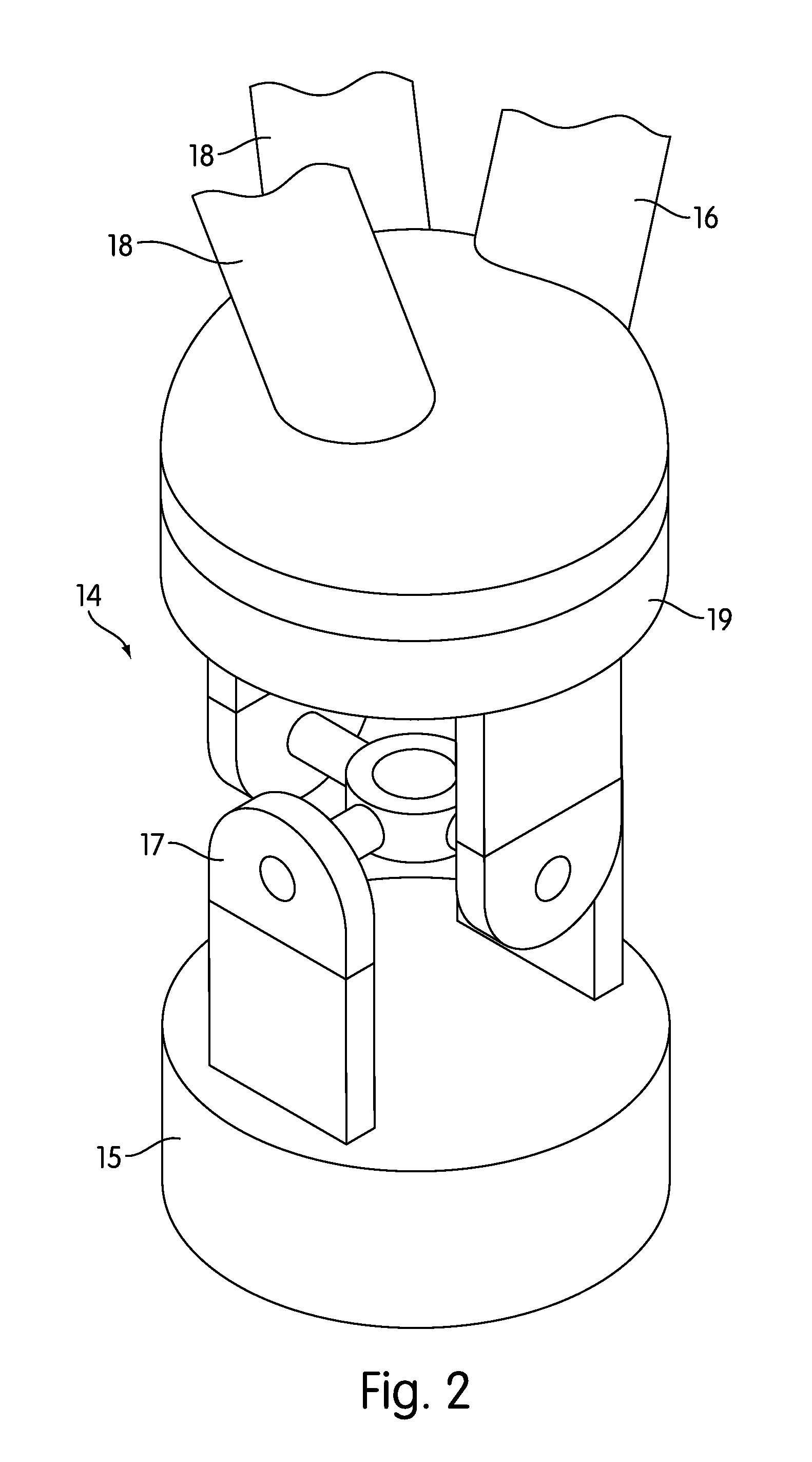
[0024]The floating underwater support structure 10 is anchored to the floor of a body of water. (In certain portions of this description, the terms “sea floor” and “seabed” may be used interchangeably and also refer generally to the floor of a body of water.) The anchor mechanism 14 that anchors the support structure 10 allows rotation and angular movement in at least two axes of motion (i.e., it allows at least two of pitch, roll, an...


PUM


Abstract

A floating underwater support structure is disclosed. The underwater support structure includes a joint capable of rotation and angular movement along two or three axes coupled to a truss. The truss is capable of sustaining loads in tension, compression, and bending, and comprises one or more elongate, rigid members. The elongate, rigid members are capable of sustaining loads in at least tension and compression. A buoyant member positioned between or around the members of the truss at a predetermined distance below the water provides a buoyant force that typically exceeds the weight of the entire structure. In deeper water, cross bracing may be provided between the members of the truss, and in particularly deep water, a single tendon may connect between the joint, typically anchored to the floor of the body of water, and the truss. The support structure may be used to support wind turbines and other structures.

Description

CROSS-REFERENCE TO RELATED APPLICATIONS[0001]This patent application claims priority to U.S. Provisional Patent Application No. 61 / 287,157, filed Dec. 16, 2009, and to U.S. Provisional Patent Application No. 61 / 314,146, filed Mar. 15, 2010. The contents of both of those applications are hereby incorporated by reference in their entireties.BACKGROUND OF THE INVENTION[0002]1. Field of the Invention[0003]The invention relates to floating underwater support structures that can support structures placed above or on the surface of a body of water, and can maintain a stable, substantially upright orientation in shallow and deep water.[0004]2. Description of Related Art[0005]Many processes, including various types of energy exploration and production, require that a floating structure be placed permanently or semi-permanently in a body of water. The manner in which these floating structures are placed and supported depends on the weight and size of the structure, the depth of the water, the...

Claims


Application Information

Patent Timeline
Patent Type & Authority Patents(United States)
IPC IPC(8): B63H1/38
CPCF03D1/0608H02K7/088H02K7/1838F05B2220/7066Y02E10/721Y02E10/725H02K2213/12F05B2240/2213Y02E10/72B63B22/00E02B17/04F03B13/12F03D9/00
Inventor SHARPLES, WILLIAM G.TRACY, CHRISTOPHER H.
Owner CLEAR PATH ENERGY
Why Eureka
Try Eureka