Power unit
a technology of power unit and power transmission path, which is applied in the direction of locomotive transmission, electric motor propulsion transmission, gearing, etc., can solve the problems of reducing the manufacturing cost of the vehicle, inhibiting the reduction of weight or downsizing, and auxiliary devices not being able to drive by the engine, so as to simplify the configuration of the first power transmission path
- Summary
- Abstract
- Description
- Claims
- Application Information
AI Technical Summary
Benefits of technology
Problems solved by technology
Method used
Image
Examples
first embodiment
[0064]A first embodiment of the present invention will be described with reference to FIGS. 1 to 12.
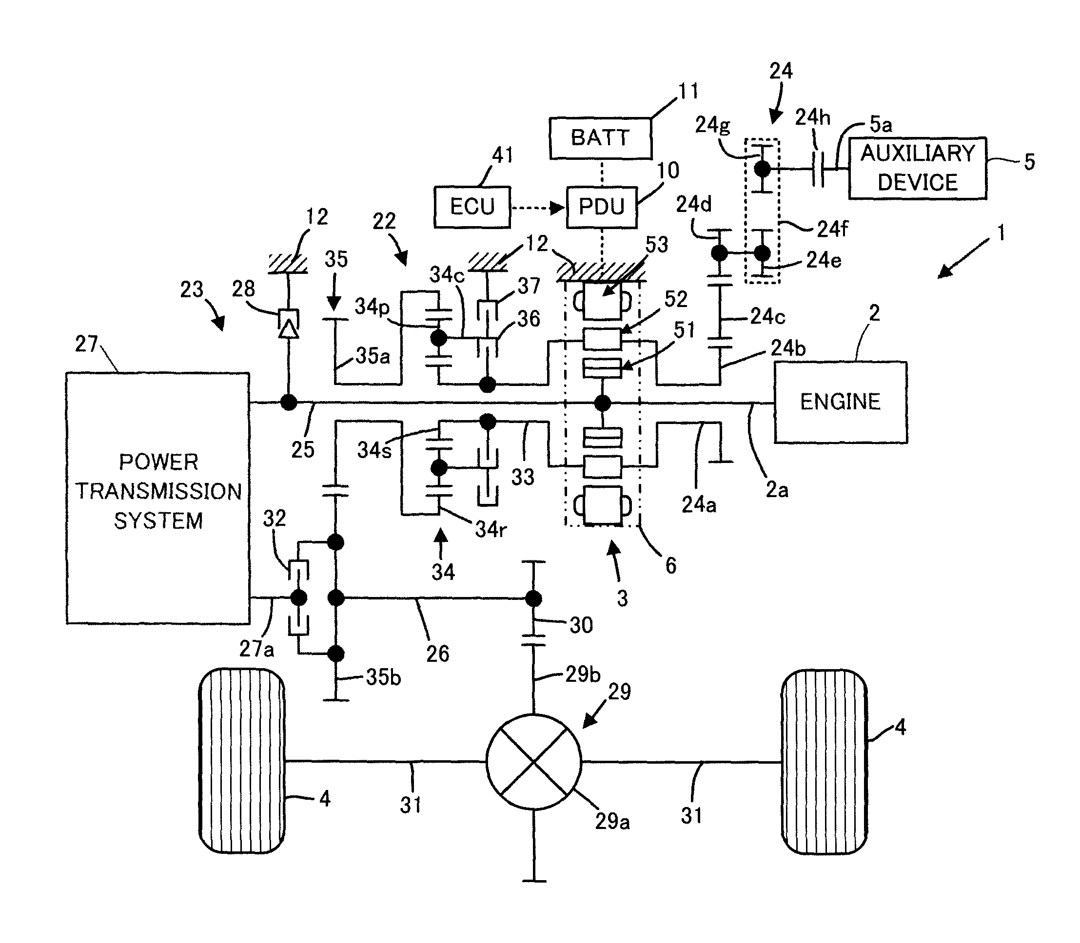
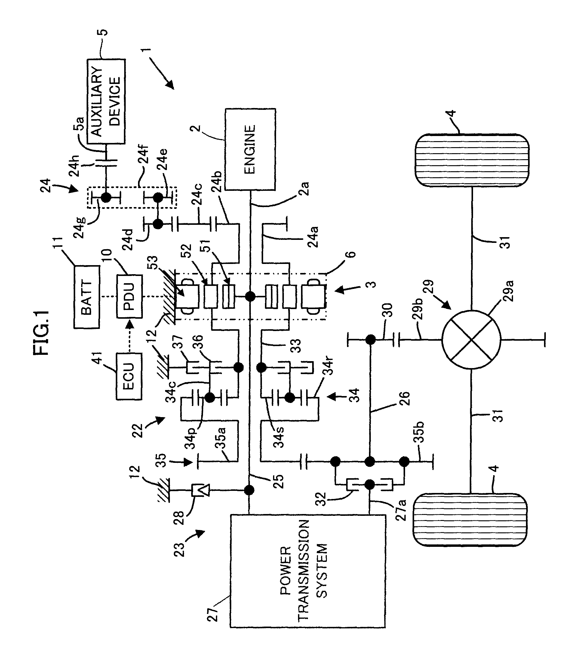
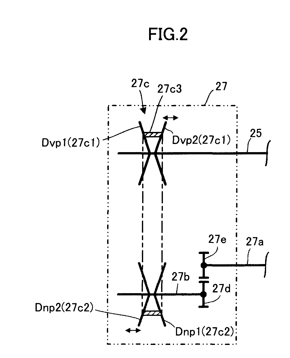
[0065]First, referring to FIGS. 1 and 2, the configuration of a power unit 1 according to this embodiment will be described.
[0066]Referring to FIG. 1, the power unit 1 according to this embodiment is a power unit mounted on a hybrid vehicle, having an engine 2 and a rotating machine 3 as power generation sources. Further, the power unit 1 is adapted to be capable of driving a pair of driving wheels 4, 4 by transmitting power of the engine 2 or the rotating machine 3 to the driving wheels 4, 4. In addition, the power unit 1 is adapted to be capable of driving an auxiliary device 5 mounted on the vehicle by transmitting the power of the engine 2 or the rotating machine 3 to the auxiliary device 5 as well as the driving wheels 4, 4. The auxiliary device 5 is, for example, an air conditioner compressor, a water pump, an oil pump, or the like.
[0067]In this embodiment, the engine 2 and the ...
second embodiment
[0210]The following describes a second embodiment of the present invention with reference to FIGS. 13 to 14. This embodiment is different from the power unit 1 of the first embodiment only in a part of the configuration of the rotating machine. More specifically, this embodiment includes a rotating machine 60 which is different from the rotating machine 3 only in a part of the configuration (the rotating machine 60 which functions as an energy dispensing / synthesizing system in the fourth invention), instead of the rotating machine 3. Therefore, in the description of this embodiment, the same components as those in the first embodiment are denoted by the same reference numerals as in the first embodiment and their description is omitted.
[0211]Referring to FIG. 13, the rotating machine 60 includes a first rotor 61 and a second rotor 62 as two bodies of rotation rotationally supported in a housing 64 of the rotating machine 60 and includes an immovable stator 63 fixed to the housing 64...
third embodiment
[0238]The following describes a third embodiment of the present invention with reference to FIGS. 15 to 17. This embodiment is different from the power unit 1 of the first embodiment only in a part of the configuration of the rotating machine. More specifically, this embodiment includes a rotating machine 70 which is different from the rotating machine 3 only in a part of the configuration (the rotating machine 70 which functions as an energy dispensing / synthesizing system in the fourth invention), instead of the rotating machine 3. Therefore, in the description of this embodiment, the same components as those in the first embodiment are denoted by the same reference numerals as in the first embodiment and their description is omitted.
[0239]While the power unit of the second embodiment includes the rotating machine 60 having two rotating machine structures, the rotating machine 70 of this embodiment has still more rotating machine structures such as, for example, three rotating mach...
PUM
 Abstract
Description
Claims
Application Information
 - R&D
- Intellectual Property
- Life Sciences
- Materials
- Tech Scout
- Unparalleled Data Quality
- Higher Quality Content
- 60% Fewer Hallucinations
Browse by: Latest US Patents, China's latest patents, Technical Efficacy Thesaurus, Application Domain, Technology Topic, Popular Technical Reports.
© 2025 PatSnap. All rights reserved.Legal|Privacy policy|Modern Slavery Act Transparency Statement|Sitemap|About US| Contact US: help@patsnap.com


