Integrated boost cavity ring generator for turbofan and turboshaft engines

a turbofan and turboshaft engine technology, applied in the direction of electric generator control, machines/engines, magnetic circuit shape/form/construction, etc., can solve the problems of difficult to allocate additional space inside the gas turbine engine in which to place components, and the shaft power transfer system does not disclose differential geared gas turbine engines. , to achieve the effect of minimizing the performance impact of the engin

Active Publication Date: 2012-06-12
GENERAL ELECTRIC CO
View PDF27 Cites 23 Cited by
  • Summary
  • Abstract
  • Description
  • Claims
  • Application Information

AI Technical Summary

Benefits of technology

[0016]The present invention provides the ability to control power extraction from the engine while minimizing the performance impact on the engine.

Problems solved by technology

When operating an aircraft engine at relatively low power levels, e.g., while idly descending from altitude, extracting this additional electrical power from the engine mechanical power may reduce the ability to operate the engine properly.
The low-pressure (LP) engine spool provides an alternate source of power transfer, however, the relatively lower speed of the LP engine spool typically requires the use of a gearbox, as slow-speed electrical generators are often larger than similarly rated electrical generators operating at higher speeds.
Also, it is difficult to allocate additional space inside the gas turbine engine in which to place components such as generators, because most of the available space inside the nacelle is utilized.
However, Hield et al. shaft power transfer system does not disclose differential geared gas turbine engines, because they direct themselves to the transfer of shaft power between two independently rotatable (i.e. not differentially-geared) engine spools.

Method used


Image

  • Integrated boost cavity ring generator for turbofan and turboshaft engines
  • Integrated boost cavity ring generator for turbofan and turboshaft engines
  • Integrated boost cavity ring generator for turbofan and turboshaft engines

Examples


Embodiment Construction

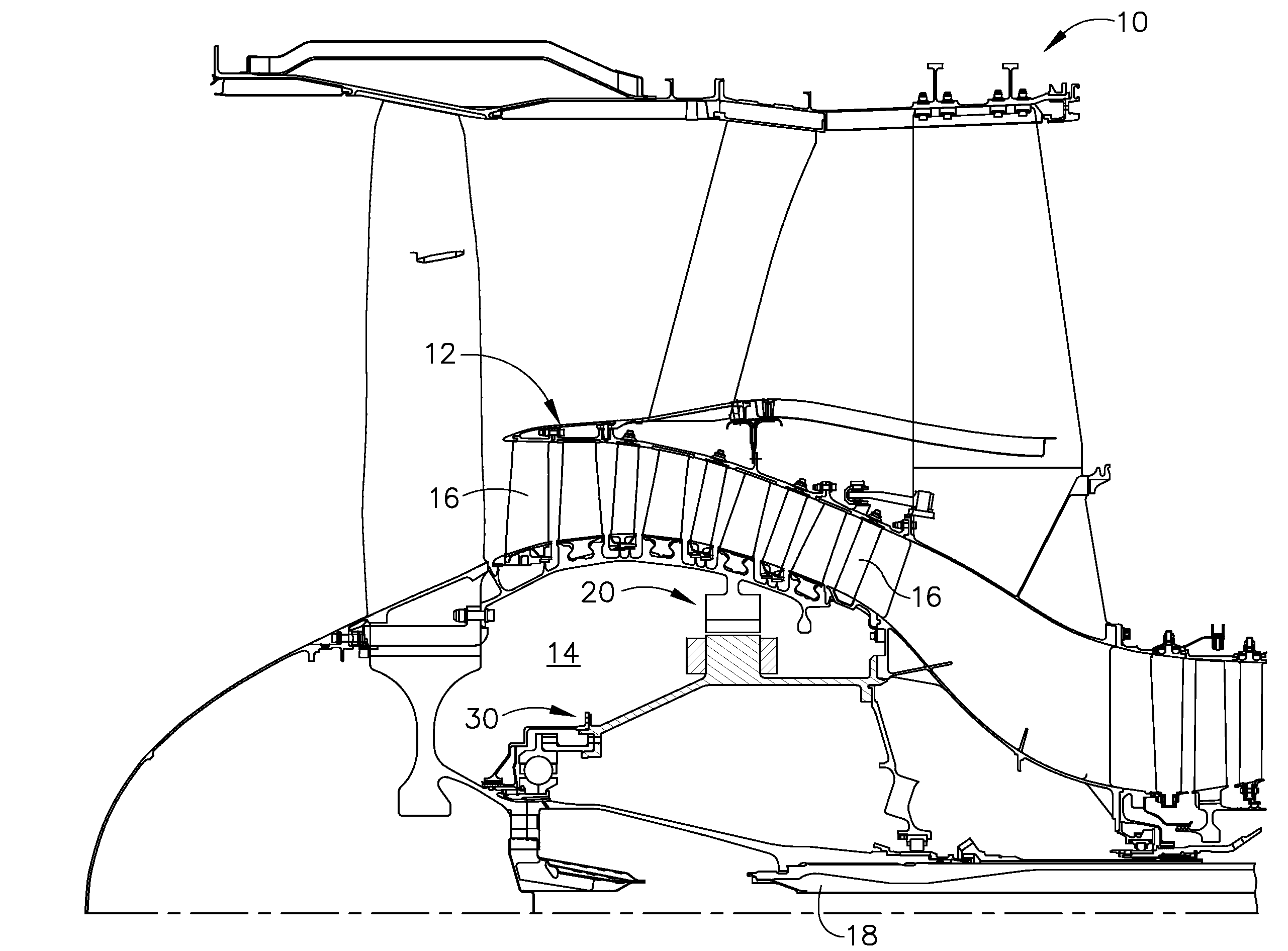
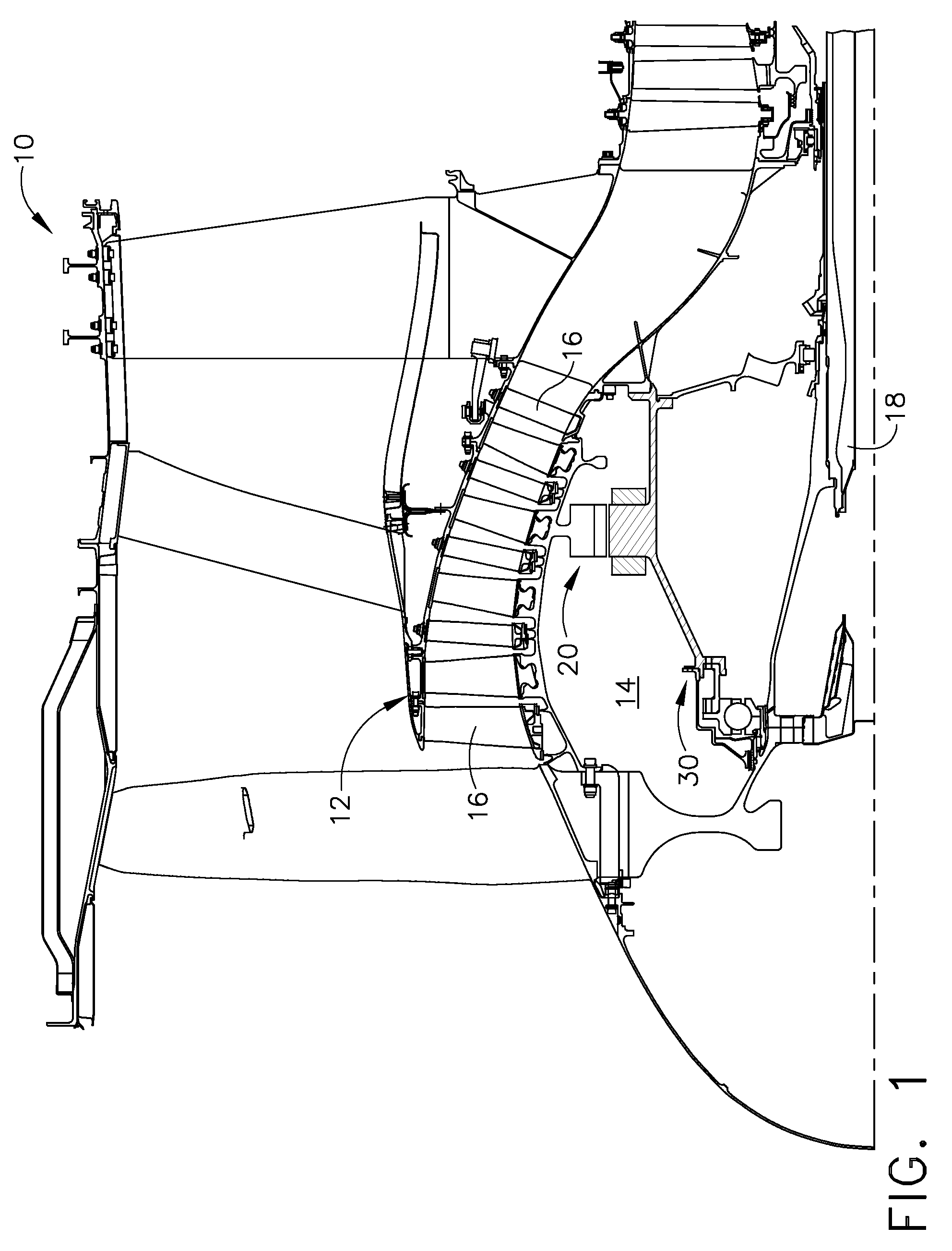
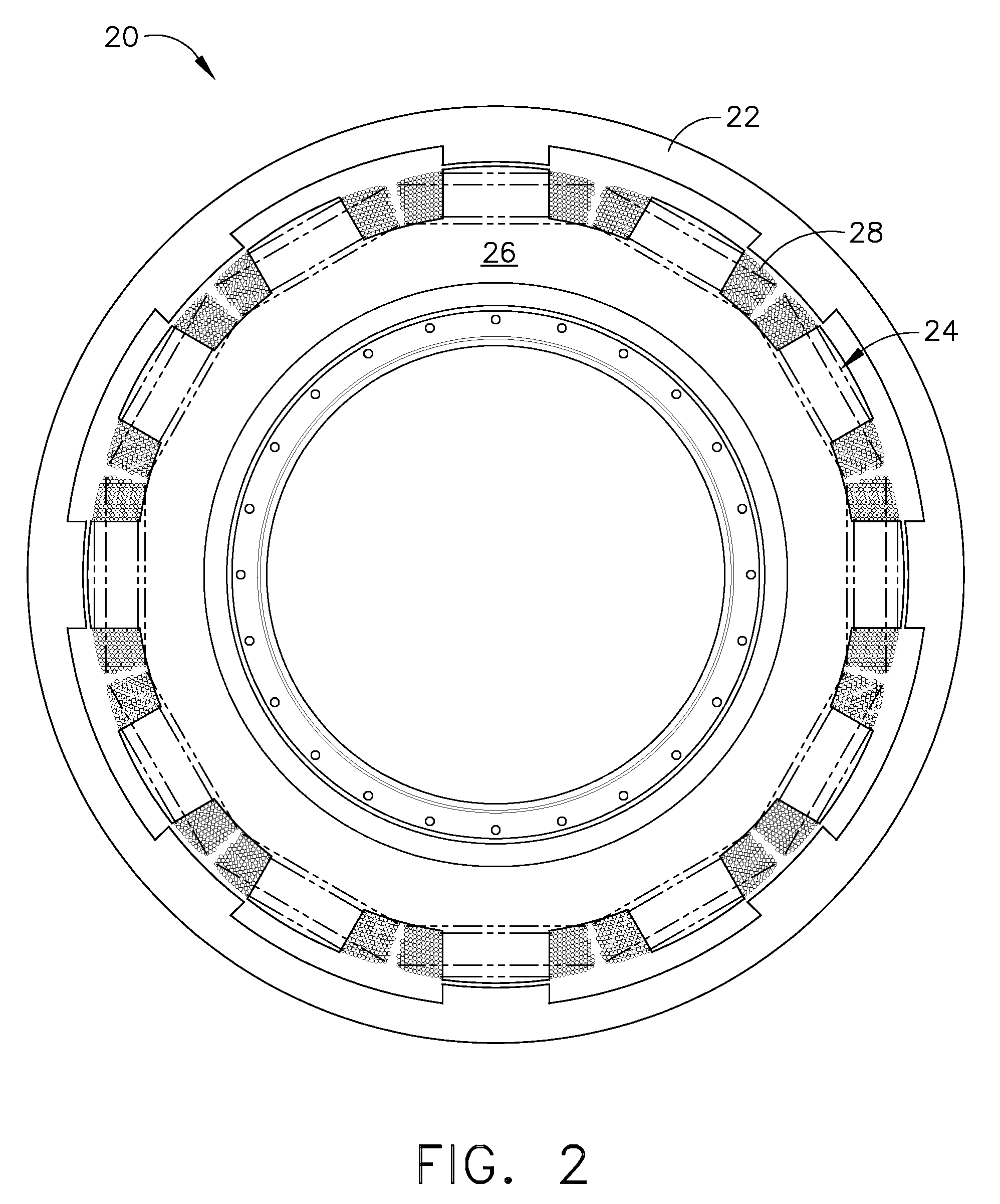
[0022]Referring to FIGS. 1 and 2, there is a turbine engine generally designated as 10. A booster section 12 includes a cavity 14 between the booster section blades 16 and the axial shaft of the engine 10. An electrical generator 20 is mounted inside the cavity 14 and extracts electrical power from the engine 10. The generator 20 is preferably a switched reluctance (SR) machine, although the invention is not limited to SR machines, as induction machines and other types of electromagnetic machines, as well as permanent magnet machines, may also be used. An inside out switched reluctance is a preferred electromagnetic machine for application in the present invention, since the rotor section of an inside out switched reluctance machine does not require cooling or field windings. While the following description is directed to an SR machine configuration, it will be understood by those skilled in the art that various electromagnetic machine configurations may be substituted for the SR ma...


PUM


Abstract

An electrical generator for extraction of electrical power from a gas turbine engine includes a rotor portion and a stator portion disposed within a booster cavity of the gas turbine engine. The rotor portion is rotatably supported about the stator portion. The stator portion rigidly is supported within the booster cavity. The rotor portion has a plurality of poles circumferentially arranged opposite the stator portion. The stator portion includes a plurality of coil portions disposed about an outer periphery of the stator portion adjacent to the stator portion. The stator and rotor portions are configured to generate electrical power when the rotor portion is rotated about the stator portion by a shaft of the gas turbine engine to induce electrical currents in the coil portions. The electrical generator extracts electric power from the turbine engine to supplement primary electrical generation sources of the engine.

Description

FIELD OF THE INVENTION[0001]The present invention is directed to a system for generating electrical power from turbofan and turboshaft engines, and more particularly to an electrical generator integrally disposed within the boost cavity of a turbofan aircraft engine.BACKGROUND OF THE INVENTION[0002]A gas turbine engine generally includes one or more compressors followed in the flow direction by a combustor and high and low pressure turbines. These engine components are arranged in serial flow communication and disposed about a longitudinal axis centerline of the engine within an annular outer casing. The compressors are driven by the respective turbines and compressor air during operation. The compressor air is mixed with fuel and ignited in the combustor for generating hot combustion gases. The combustion gases flow through the high and low pressure turbines, which extract the energy generated by the hot combustion gases for driving the compressors, and for producing auxiliary outp...

Claims


Application Information

Patent Timeline
Patent Type & Authority Patents(United States)
IPC IPC(8): H02P9/00
CPCF01D15/10F05D2220/7642F05D2220/76F05D2220/766F05D2220/768
Inventor KERN, JOHN M.QU, RONGHAIYOUNG, CRAIG DOUGLAS
Owner GENERAL ELECTRIC CO
Why Eureka
Try Eureka