Electric power tool

a technology of electric power tools and power tools, applied in the direction of electronic commutators, motor/generator/converter stoppers, dynamo-electric converter control, etc., can solve the problems of large error, needing to be exchanged, spark generation, etc., and achieve the effect of free from maintenance load

Active Publication Date: 2012-06-12
MAX CO LTD
View PDF33 Cites 42 Cited by
  • Summary
  • Abstract
  • Description
  • Claims
  • Application Information

AI Technical Summary

Benefits of technology

[0010]One or more embodiments of the invention provide an electric power tool capable of performing stabilized functions over an extended period of time and free from load of maintenance by using a brushless motor instead of a brush motor.
[0012]According to the above described electric power tool, it is possible to judge the rotation number and the rotation position of the rotor from the detection signal of the sensor. Therefore, it becomes unnecessary to provide many position sensors for detecting working state of the working part, thus enabling the components to be reduced in number, and the positional information having high analyzing ability depending on the rotation number of the motor can be obtained. As the results, a step for adjusting the position sensors, confirmation of works, and so on can be eliminated, and working efficiency is enhanced. At the same time, troubles due to damage of the position sensors will not occur, and hence, it is possible to provide the electric power tool of enhanced quality.
[0014]According to the above described electric power tool, it is possible to drive the motor with a large driving current in case where a large torque is required (when rapid acceleration is required, loaded torque is large), and with a small driving current in case where a small torque would be sufficient. As the results, consumption of the electric current can be depressed, and the motor can be restrained from being heated.
[0016]According to the above described electric power tool, by using the brushless motor instead of the brush motor, the brush itself which is a factor for a useful life of the motor can be eliminated, and hence, it is possible to remarkably prolong the life of the electric power tool.
[0020]According to the above described electric power tool, efficient operation can be made in both the normal rotation and the reverse rotation. Because the electric current for the required torque can be made small, the limited value can be set to be low. Therefore, it is possible to further expect such advantages that consumption of the current is decreased, and the motor is restrained from being heated.

Problems solved by technology

Moreover, in case of judging a position of the motor by monitoring time on the basis of a certain reference point, there is such a problem that a large error may occur in the judged position, because a motor speed varies according to a change of battery voltage.
Further, when abrupt acceleration and deceleration are repeated in a short period, there is such anxiety that the following problems may occur.
When polarity of the brush is switched during the rotation for rapidly reversing the rotation, sparks are generated, and the brush may be worn and need to be exchanged.
(2) Until life of the motor terminates, performances of the motor (rotation number, acceleration) are deteriorated, and hence, deterioration of performances of the machine is unavoidable.
(3) The machine cannot be used in an efficient state when the performances of the motor have been deteriorated, and power consumption is increased.
As the results, useful life of the battery is decreased.
For this reason, in case where the motor is set so as to efficiently work in the normal rotation, the motor will not work efficiently in the reverse rotation, generating large noises.
Therefore, there has been such a problem that efficient operation cannot be expected in controlling the brush motor, when the normal rotation and the reverse rotation are mixed.

Method used


Image

  • Electric power tool
  • Electric power tool
  • Electric power tool

Examples


Embodiment Construction

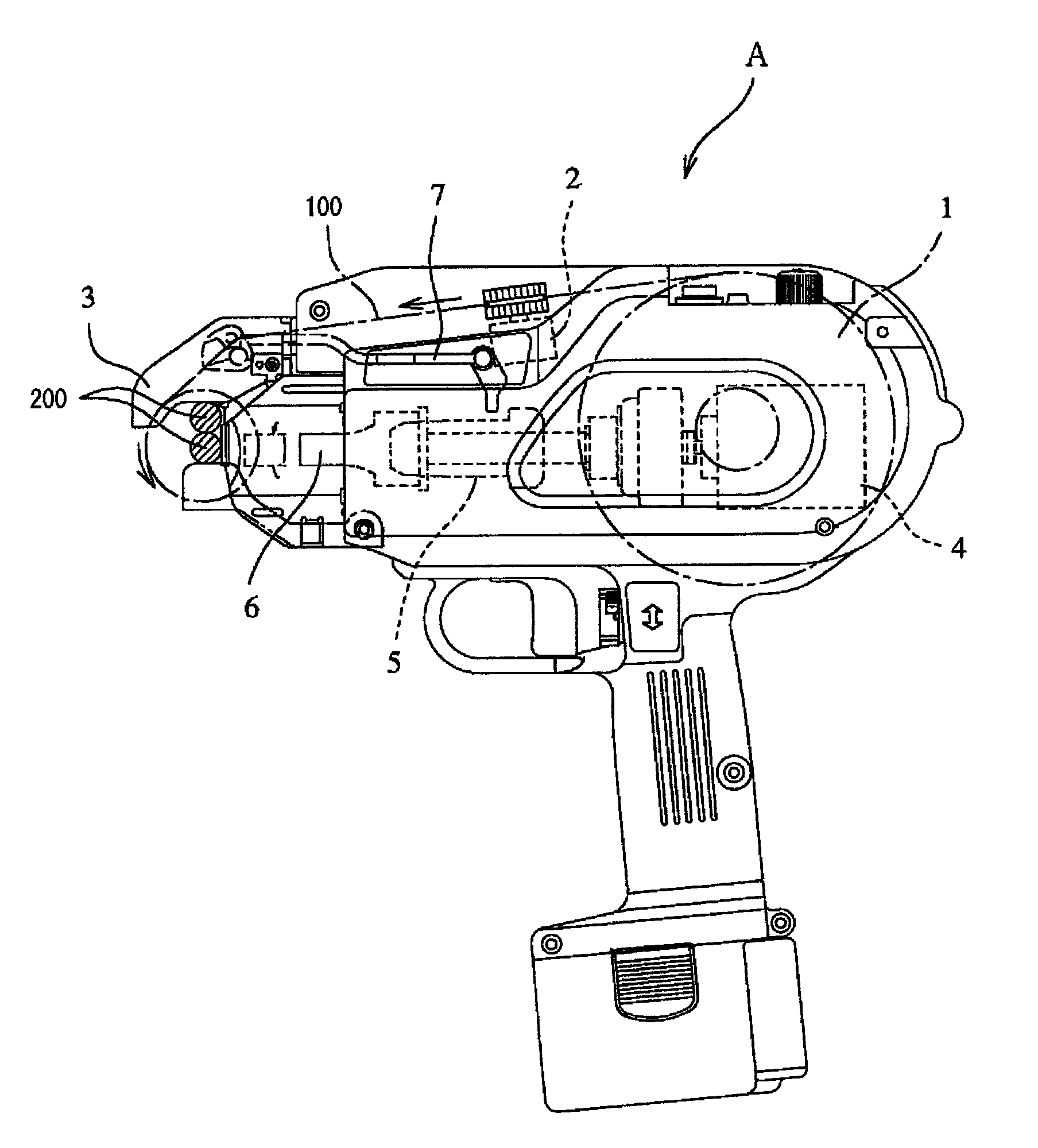
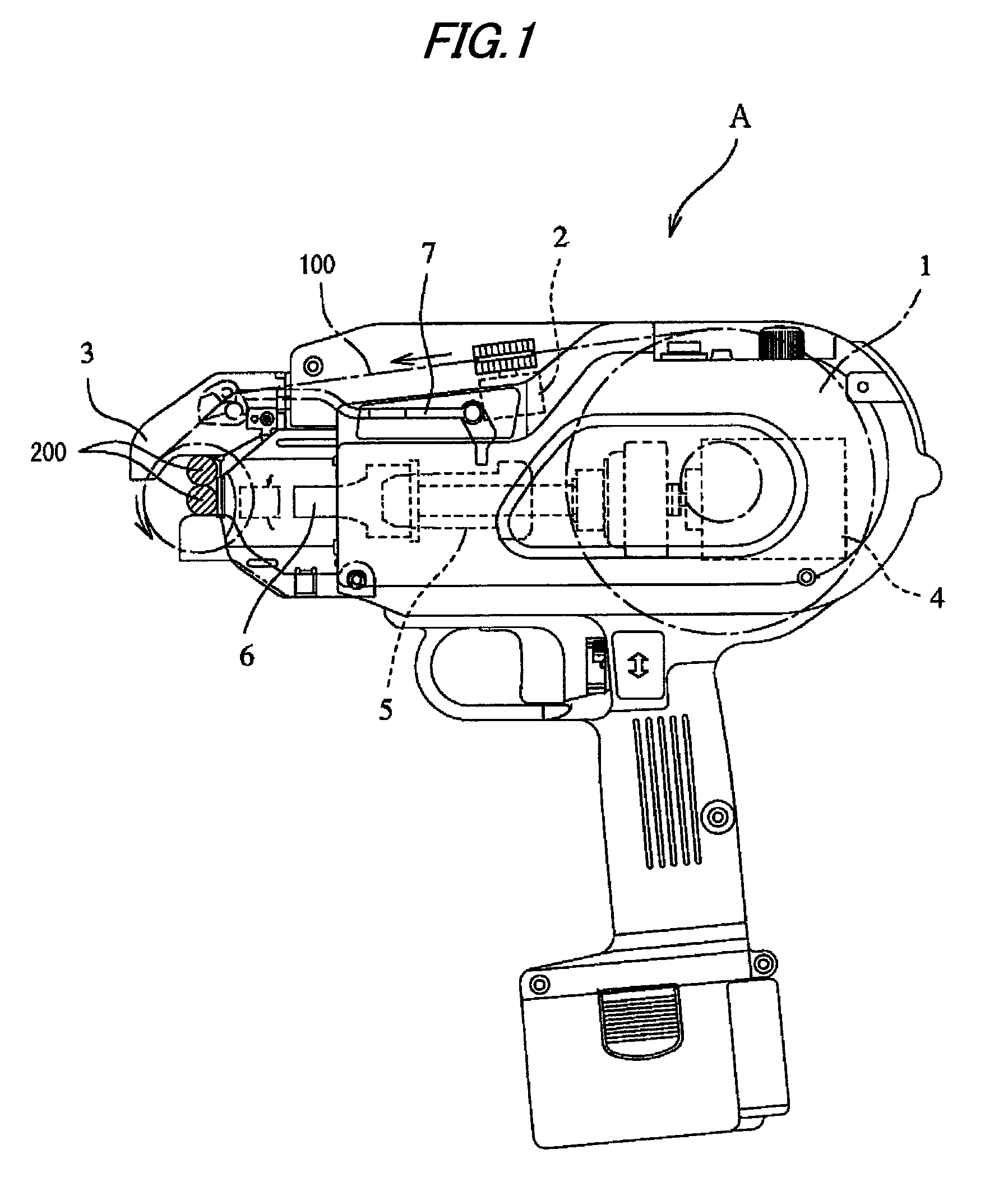
[0042]FIG. 1 shows an electric power tool “A” in an embodiment according to the invention. In the following description, a case where the invention is applied to a reinforcing bar binding machine for binding reinforcing bars will be described, as a exemplary embodiment of the invention. In this reinforcing bar binding machine “A”, a wire 100 is fed from a cartridge 1 to a guide arm 3 by a feed motor 2. After the wire 100 has been wound around reinforcing bars 200, a twisting motor 4 is rotated to bind the reinforcing bars with the wire 100. The feed motor 2 is rotated in a normal direction thereby to wind the wire 100 around the reinforcing bars. Then, the twisting motor 4 is rotated in the normal direction to move a sleeve (a work part) 5 forward by sliding, and a hook 6 provided at a distal end of the sleeve 5 clamps the wire 100. Thereafter, the feed motor 2 is rotated in a reverse direction to remove slack of the wire 100. Then, the twisting motor 4 is rotated again in the norma...


PUM


Abstract

An electric power tool “A” operates a working part 5 by repeating rotation of a motor 4 in a normal direction and in a reverse direction one or more times. The motor 4 includes a brushless motor. Sensors H for detecting a position of a rotor 15 are provided on the motor 4 so as to be advanced by an electrical angle of 30°±θ° from an intermediate position between respective stator teeth 16 in a direction of the normal rotation of the rotor 15. A control part 20 for controlling the rotation of the motor 4 controls a driving signal of the motor 4 based on the results of detection by the sensors H. Moreover, the control part 20 selects a detection signal of the sensors H so that relation between the rotor 15 and the detection signal of the sensors H is equivalent in either of the normal rotation and the reverse rotation of the rotor 15.

Description

TECHNICAL FIELD[0001]The present invention relates to an electric power tool, and more particularly, to the electric power tool in which a working part is actuated by rotating a motor in normal and reverse directions and a brushless motor is used as the motor.BACKGROUND ART[0002]As an electric power tool in which a working part is actuated by rotating a motor in normal and reverse directions, there has been known a reinforcing bar binding machine for binding reinforcing bars with a wire (for example, JP-A-2003-267307). In this reinforcing bar binding machine, a brush motor has been generally used as a drive source. The reason why this brush motor is used is because high torque can be obtained in spite of a small size, and the machine can be downsized by using the brush motor.[0003]In the conventional reinforcing bar binding machine as described above, position sensors are disposed at several positions in the working part as means for determining timing for switching the rotation of ...

Claims


Application Information

Patent Timeline
Patent Type & Authority Patents(United States)
IPC IPC(8): B25F5/00H02P6/08H02P6/06H02P6/16H02P6/22
CPCB25F5/02H02P6/22E04G21/122Y10S388/937E04G21/123B25B25/00E04G21/12
Inventor KATOU, KOUJITAKEUCHI, KAZUYAKUSAKARI, ICHIROITAGAKI, OSAMUNAGAOKA, TAKAHIRO
Owner MAX CO LTD
Why Eureka
Try Eureka