Switched-capacitor amplifier circuit

a technology of switching capacitors and amplifier circuits, which is applied in the direction of dc-amplifiers with dc-coupled stages, differential amplifiers, and amplifiers with semiconductor devices/discharge tubes. it can solve the problems of disadvantageous output error of known cds amplifiers in the range of one-half of lsb

Inactive Publication Date: 2012-06-12
TAIWAN SEMICON MFG CO LTD
View PDF12 Cites 30 Cited by
  • Summary
  • Abstract
  • Description
  • Claims
  • Application Information

AI Technical Summary

Problems solved by technology

In other words, a non-rail-to-rail OpAmp cannot properly amplify a differential signal that has a common-mode voltage near either rail because the non-rail-to-rail OpAmp has a limited common-mode range.
However, disadvantageously, the output of the known CDS amplifier 102 is not immune to VCM.
However, when the common-mode voltage of the input signal is near VDD or VSS, the output error of the known CDS amplifier 102 may be disadvantageously in the range of one-half of a LSB when the number of bits of resolution is 12-bits or fewer.
A disadvantage of the known CDS amplifier 102 is that, during phase two, the input common-mode voltage VCM affects the input of the OpAmp 160.
However, when the common-mode voltage is near VDD or near VSS, such pulsing causes an error at the output of a non-rail-to-rail OpAmp.

Method used


Image

  • Switched-capacitor amplifier circuit
  • Switched-capacitor amplifier circuit
  • Switched-capacitor amplifier circuit

Examples


Embodiment Construction

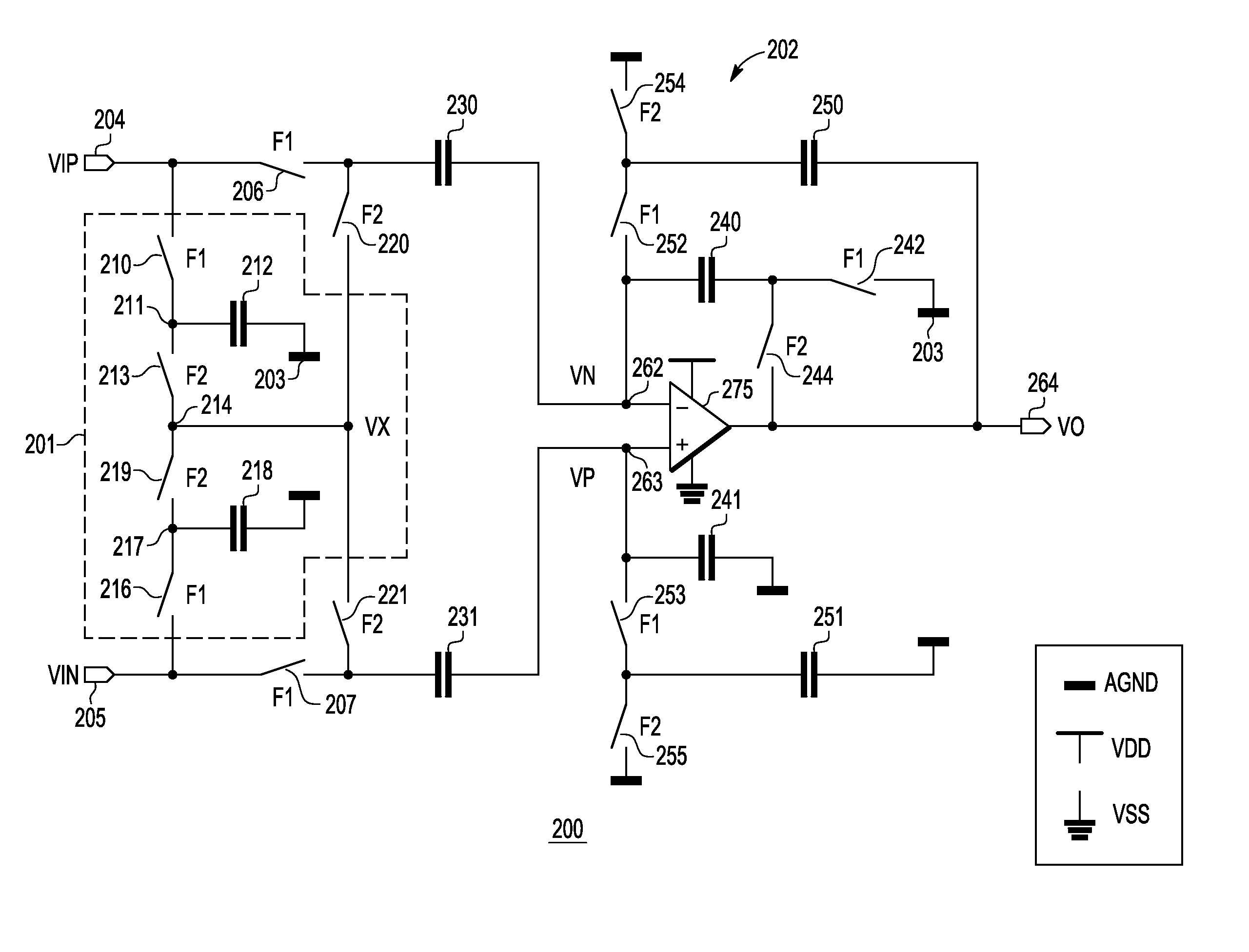
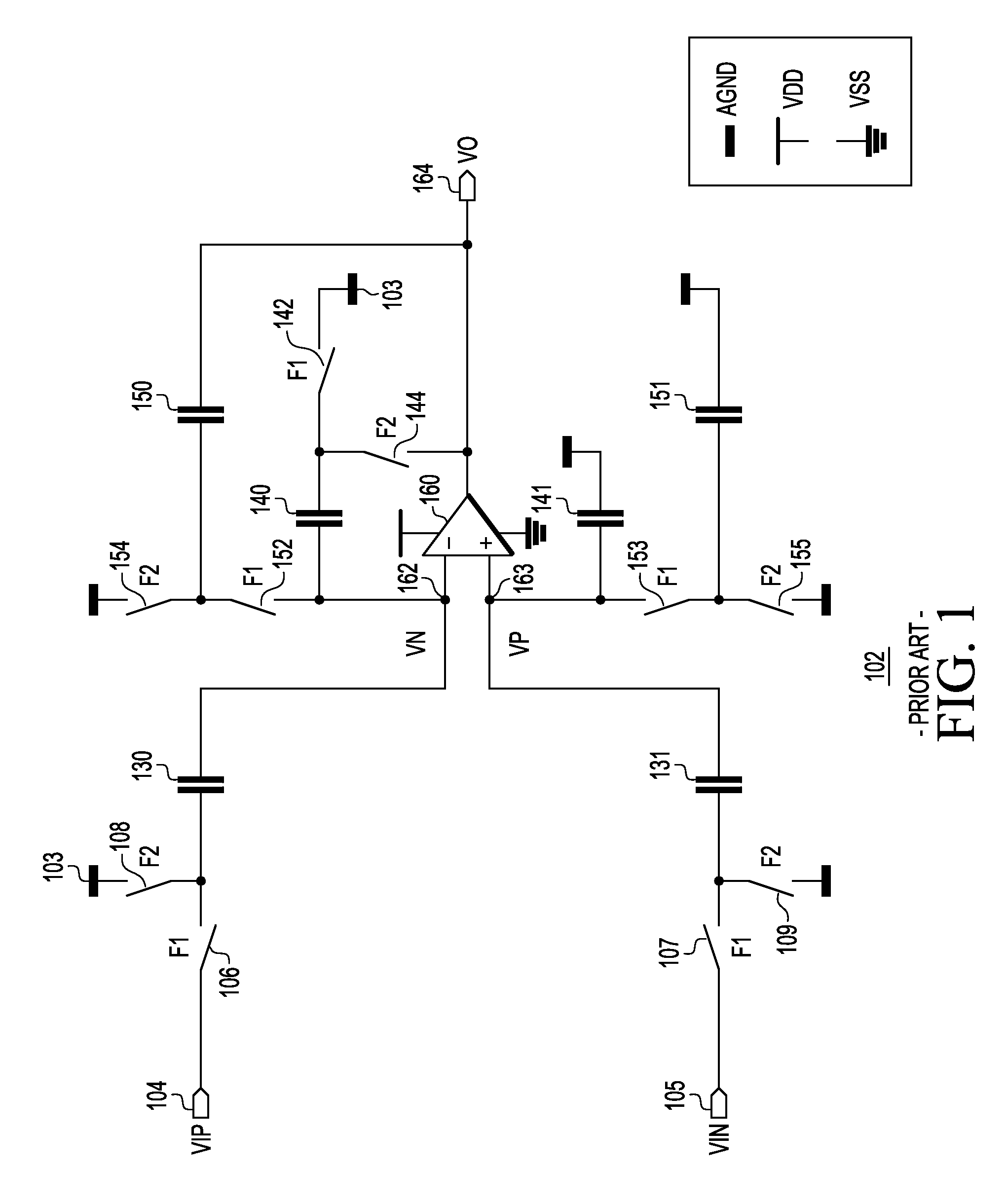
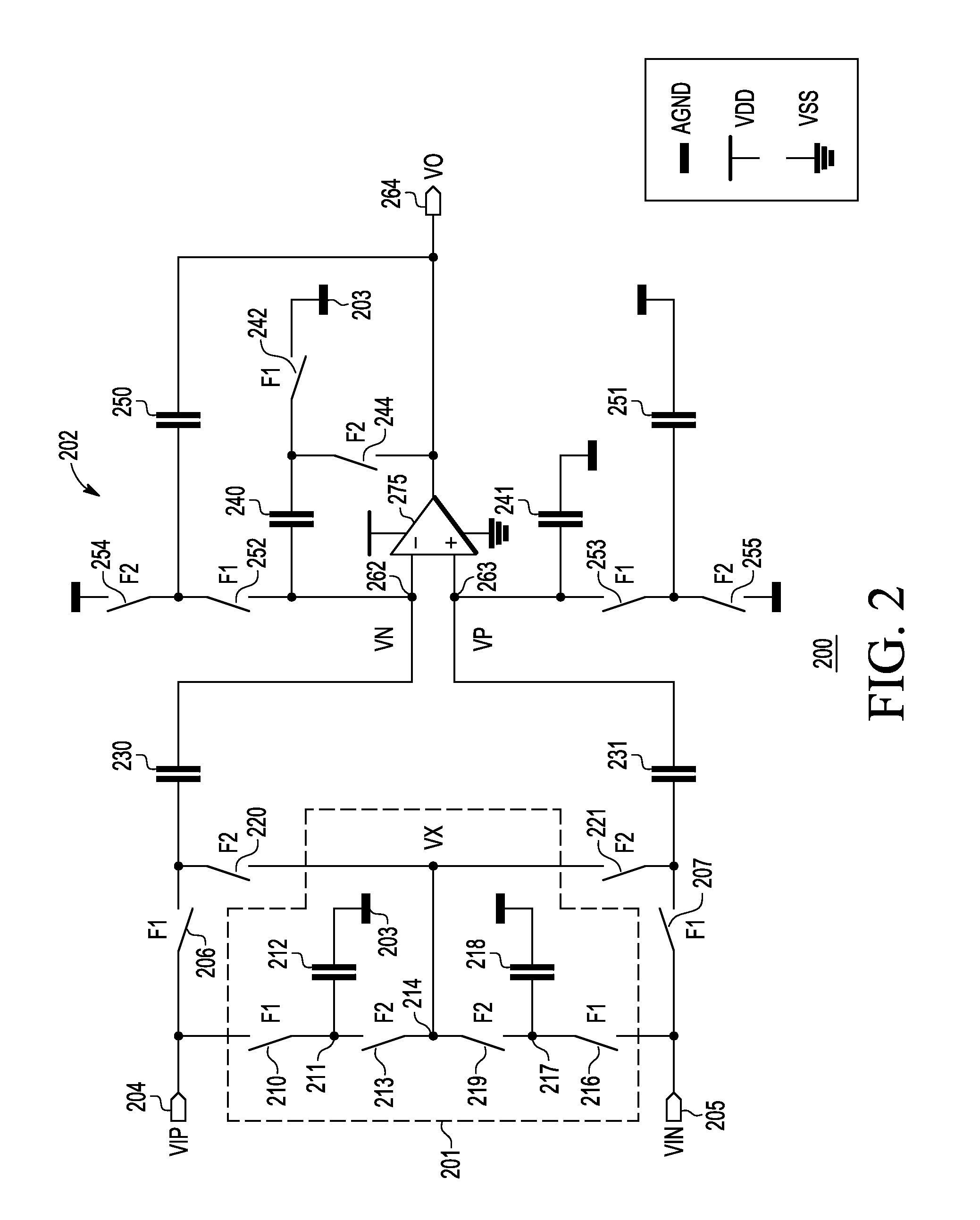
[0020]A switched-capacitor amplifier that lacks a rail-to-rail OpAmp (and uses instead a non-rail-to-rail OpAmp) needs a rail-to-rail input circuit so that the switched-capacitor amplifier can properly amplify an input signal that has a common-mode voltage near either rail of a power supply. FIG. 2 is a schematic diagram of a switched-capacitor amplifier circuit (hereinafter “amplifier circuit”) 200 in accordance with the invention. The amplifier circuit 200 includes a switched-capacitor, rail-to-rail input circuit (hereinafter “input network”) 201 and a switched-capacitor amplifier (hereinafter “switched-capacitor amplifier”) 202. In one embodiment, the switched-capacitor amplifier 202 uses a correlated double-sampling (CDS) technique.

[0021]The switched-capacitor amplifier 202 comprises a first sampling switch 206 with one terminal connected to a VIP input terminal 204 and another terminal connected to a first sampling capacitor 230, and a second sampling switch 207 with one termin...


PUM


Abstract

A switched-capacitor amplifier circuit (200 and 300) with rail-to-rail capability without requiring a rail-to-rail operational amplifier includes a switched-capacitor amplifier (202 and 302) and an input network (201) coupled to the switched-capacitor amplifier. The switched-capacitor amplifier includes a non-rail-to-rail operational amplifier (275 and 375). The input network prevents the non-rail-to-rail operational amplifier from receiving an input differential signal that has a common-mode voltage at or near rails of the non-rail-to-rail operational amplifier. Voltages at input terminals of the operational amplifier remain near analog ground, which is an arbitrary voltage level between the rails, during both phases of switching in the switched-capacitor amplifier. In one embodiment, the switched-capacitor amplifier uses a correlated double sampling technique.

Description

BACKGROUND[0001]1. Field[0002]This invention relates generally to switched-capacitor circuits and more specifically to a switched-capacitor amplifier circuit that may be disposed on an integrated circuit.[0003]2. Related Art[0004]A switched-capacitor circuit is a circuit that provides signals that are discrete in time and continuous in voltage amplitude. Correlated double sampling (CDS) is a technique used with switched-capacitor circuits to measure small, slowly changing signals in the presence of large amounts of low frequency (1 / f) noise and direct current (DC) input offset voltage. The CDS technique is a particular type of auto-zero technique, in which noise and a DC input offset voltage are sampled twice in each clock period. Switched-capacitor amplifiers often use the CDS technique to compensate for non-idealities of an operational amplifier (OpAmp) in the switched-capacitor circuit such as finite open-loop gain (hereinafter “OpAmp gain”) and DC input offset voltage. In a non-...

Claims


Application Information

Patent Timeline
Patent Type & Authority Patents(United States)
IPC IPC(8): H03F1/02
CPCH03F3/45475H03F2200/81H03F2203/45514H03F2203/45551
Inventor VILAS BOAS, ANDRE LUISMANSANO, ANDRE L. R.OLMOS, ALFREDODE LACERDA, FABIO
Owner TAIWAN SEMICON MFG CO LTD
Why Eureka
Try Eureka