Method for stopping a hydrogen generator by controlling water supply to a reformer

a technology of hydrogen generator and reformer, which is applied in the direction of electrochemical generator, chemistry apparatus and processes, sustainable manufacturing/processing, etc., can solve the problems of inactive gas not being supplied from any infrastructure, the catalytic activity of the catalyst, the cu—zn based catalyst used by the above reaction portions may deteriorate by oxidation, and the electric power generation property of the fuel cell deteriorates, etc., to suppress the rapid pressure increase in the hydrogen generator, the reformer temperatur

Active Publication Date: 2012-06-19
PANASONIC CORP
View PDF13 Cites 0 Cited by
  • Summary
  • Abstract
  • Description
  • Claims
  • Application Information

AI Technical Summary

Benefits of technology

[0022]In accordance with the hydrogen generator of the present invention, the fuel cell power generating system including the hydrogen generator, and the method for stopping the hydrogen generator, the temperature of the reformer is quickly decreased by the water evaporation when stopping the hydrogen generator, so that the stop operation of the hydrogen generator can be quickly terminated while suppressing rapid pressure increase in the hydrogen generator. Moreover, the operation of the raw material supplier is stopped, but the operation of the water supplier is continued to generate the steam, so that while causing a replacement reaction for replacing the hydrogen-containing gas in the hydrogen generator with the steam, the combustion state of the heater can be detected to recognize a replacement state of the hydrogen-containing gas. Further, the hydrogen generator can be stopped without using the inactive gas, such as nitrogen. In addition, the fuel cell power generating system can be easily operated even at a place where the infrastructure of the inactive gas, such as the nitrogen gas, is not built.

Problems solved by technology

If the carbon monoxide concentration of the hydrogen-containing gas is high, an electric power generation property of the fuel cell deteriorates.
Catalytic activities of the catalysts, such as the Cu—Zn based catalyst, used by the above reaction portions may deteriorate by oxidation.
However, as with the hydrogen-containing gas, the inactive gas is not supplied from any infrastructure.
Especially, the inactive gas cannot be easily utilized in the distributed power generating system.

Method used


Image

  • Method for stopping a hydrogen generator by controlling water supply to a reformer
  • Method for stopping a hydrogen generator by controlling water supply to a reformer
  • Method for stopping a hydrogen generator by controlling water supply to a reformer

Examples


embodiment 1

[0054

[0055]Configuration of Fuel Cell Power Generating System

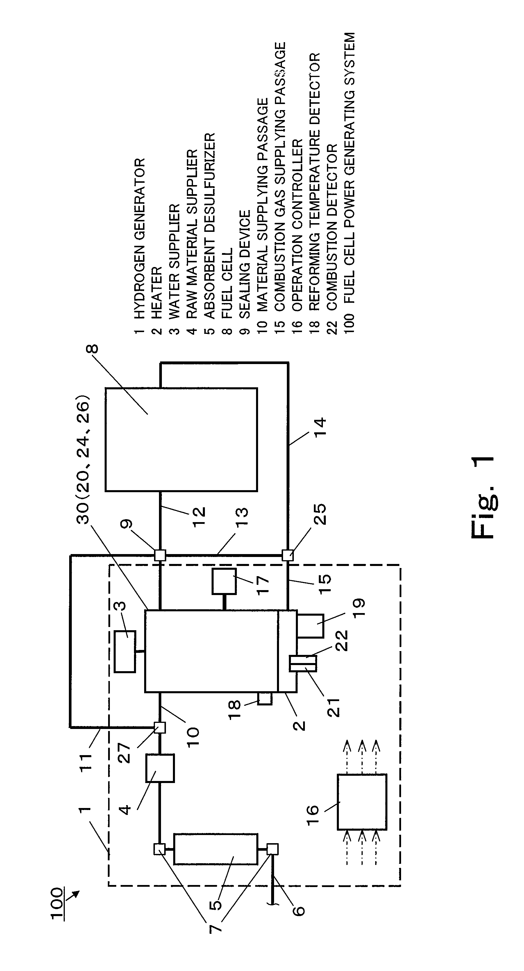
[0056]FIG. 1 is a schematic diagram showing a fuel cell power generating system 100 in Embodiment 1 of the present invention. As shown in FIG. 1, the fuel cell power generating system 100 in Embodiment 1 includes: a hydrogen generator 1 configured to generate a hydrogen-containing gas; a fuel cell 8 configured to generate electric power using the hydrogen-containing gas supplied from the hydrogen generator 1; a hydrogen-containing gas supplying passage 12 through which the hydrogen-containing gas is supplied from the hydrogen generator 1 to the fuel cell 8; an off gas passage 14 through which a hydrogen off gas discharged from the fuel cell 8 is introduced to the hydrogen generator 1; and a combustion gas supplying passage 15 through which a combustion gas is supplied to the hydrogen generator 1.

[0057]A sealing device 9 configured to stop the supply of the hydrogen-containing gas from the hydrogen generator 1 is provided o...

embodiment 2

[0104

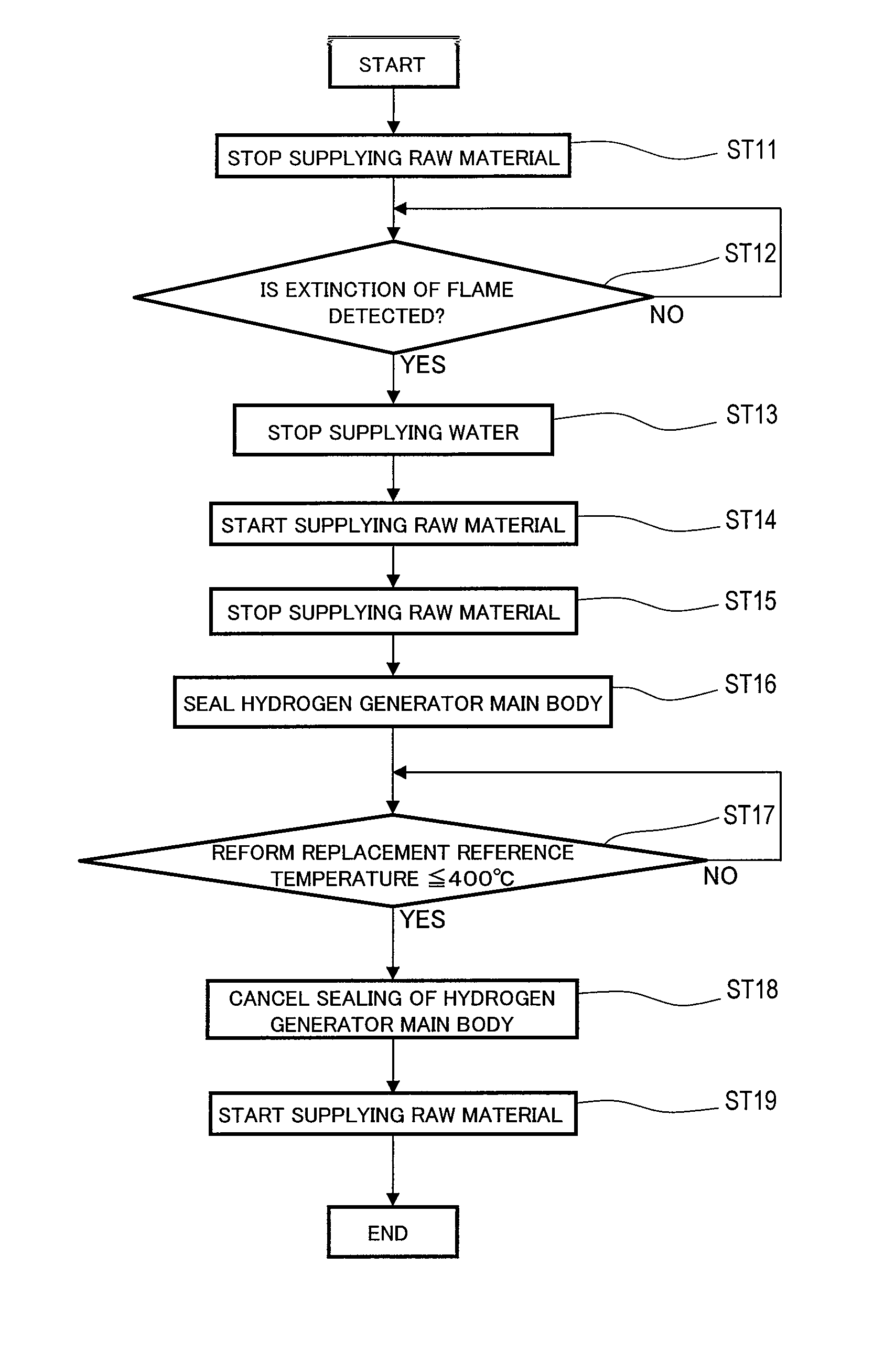
[0105]A fuel cell power generating system 200 in Embodiment 2 of the present invention will be explained. The fuel cell power generating system 200 in Embodiment 2 of the present invention is different from the fuel cell power generating system 100 in Embodiment 1 in that the reformer 20 includes a Ni-based reforming catalyst. The components other than the reformer 20 are substantially the same as those in Embodiment 1, so that detailed explanations thereof are omitted.

[0106]Start-Up and Normal Drive Operations of Fuel Cell Power Generating System

[0107]The start-up and normal drive operations of the fuel cell power generating system 200 in Embodiment 2 are the same as those in Embodiment 1, so that explanations thereof are omitted.

[0108]Stop Drive Operation of Fuel Cell Power Generating System 200

[0109]The stop drive operation of the fuel cell power generating system 200 in Embodiment 2 will be explained.

[0110]As with Embodiment 1, by the command from the operation controller 1...


PUM

PropertyMeasurementUnit
temperatureaaaaaaaaaa
combustion detectoraaaaaaaaaa

Abstract

A hydrogen generator includes: a reformer configured to generate a hydrogen-containing gas by a reforming reaction between a raw material and water; a heater configured to combust at least a part of the hydrogen-containing gas to supply heat necessary for the reforming reaction to the reformer; a combustion detector configured to detect a combustion state of the heater; a raw material supplier configured to supply the raw material; a water supplier configured to supply the water; and an operation controller. When stopping the hydrogen generator, the operation controller causes the raw material supplier to stop operating, the water supplier to stop operating in a case where the combustion detector detects extinction of flame, and the raw material supplier to start operating to supply the raw material to the hydrogen generator in a case where the reforming temperature detector detects a temperature equal to or lower than a reference temperature.

Description

RELATED APPLICATIONS[0001]This application is the U.S. National Phase under 35 U.S.C. §371 of International Application No. PCT / JP2008 / 003916, filed on Dec. 24, 2008, which in turn claims the benefit of Japanese Application No. 2008-007696, filed on Jan. 17, 2008, the disclosures of which Applications are incorporated by reference herein.TECHNICAL FIELD[0002]The present invention relates to a hydrogen generator configured to generate a hydrogen-containing gas with a low carbon monoxide concentration from, for example, a fossil material, a fuel cell power generating system including the hydrogen generator, and a method for stopping the hydrogen generator.BACKGROUND ART[0003]A fuel cell power generating system is a system configured to generate electric power such that a hydrogen-containing gas and an oxygen-containing gas are supplied to a fuel cell stack (hereinafter referred to as “fuel cell”) that is a main body of a power generating portion, and a chemical energy generated by an ...

Claims


Application Information

Patent Timeline
Patent Type & Authority Patents(United States)
IPC IPC(8): H01M8/06
CPCC01B3/384C01B3/48H01M8/0612C01B2203/0233C01B2203/0283C01B2203/044C01B2203/047C01B2203/066C01B2203/0811C01B2203/0822C01B2203/0827C01B2203/1058C01B2203/1064C01B2203/1076C01B2203/1258C01B2203/1288C01B2203/1604C01B2203/1609C01B2203/1619C01B2203/169Y02E60/50Y02P20/10
Inventor UKAI, KUNIHIROKANI, YUKIMUNE
Owner PANASONIC CORP
Why Eureka
Try Eureka