Reducing the core-end heating in large power generators

a technology of large power generators and core-end heating, which is applied in the direction of dynamo-electric machines, electrical equipment, magnetic circuit shapes/forms/construction, etc., can solve the problems of increasing losses, core failure, and generators operating at lower power

Inactive Publication Date: 2012-06-19
RAO DANTAM K
View PDF34 Cites 9 Cited by
  • Summary
  • Abstract
  • Description
  • Claims
  • Application Information

AI Technical Summary

Problems solved by technology

Ensuring that temperatures of all hot spots in all flux receivers in all abnormal conditions are within design limits (to prevent derating of the generator) is a major challenge to the core-end designer.
The end laminations also carry the useless fringe-flux in addition to the usable main flux; hence, the flux density in them is so close to the saturation limit that excess flux may spill into air; this induces more eddy current that can overheat, forcing the generator to operate at lower power rating.
Further, if the insulative coating on the end-lamination surfaces is defective and prone to shorts, the exciting voltage of the fringe-flux drives eddy currents through the shorts and can melt the iron; such microscopic shorts burn the insulation around the hot spot, propagating the melt zone, leading to core failure.
However, in one abnormal condition—termed leading phase angle—both magnets attract, so the stator magnet invites more flux from rotating magnet; so rotating magnet's axial component saturates the end-iron and overheats the end-laminations.
However, there are some unresolved issues. a) The effect is one of redistribution of axial flux, rather than its reduction, so the lower peak flux in the conical gap is accompanied by a rise elsewhere per Mecrow (1989). b) End-stepping requires higher excitation current, increasing losses in the rotor per U.S. Pat. Nos. 6,525,444 and 7,057,324. c) End-stepping reduces the clamping pressure in the bar and tooth tip, which could make them, rattle and break. d) Gradients in the axial flux induce additional eddy heat. e) Abrupt steps in the flow could result in coolant-starved areas creating new hot spots. f) More eddy current is induced inside the bar strands creating new hot spots; to counter thi

Method used


Image

  • Reducing the core-end heating in large power generators
  • Reducing the core-end heating in large power generators
  • Reducing the core-end heating in large power generators

Examples


Embodiment Construction

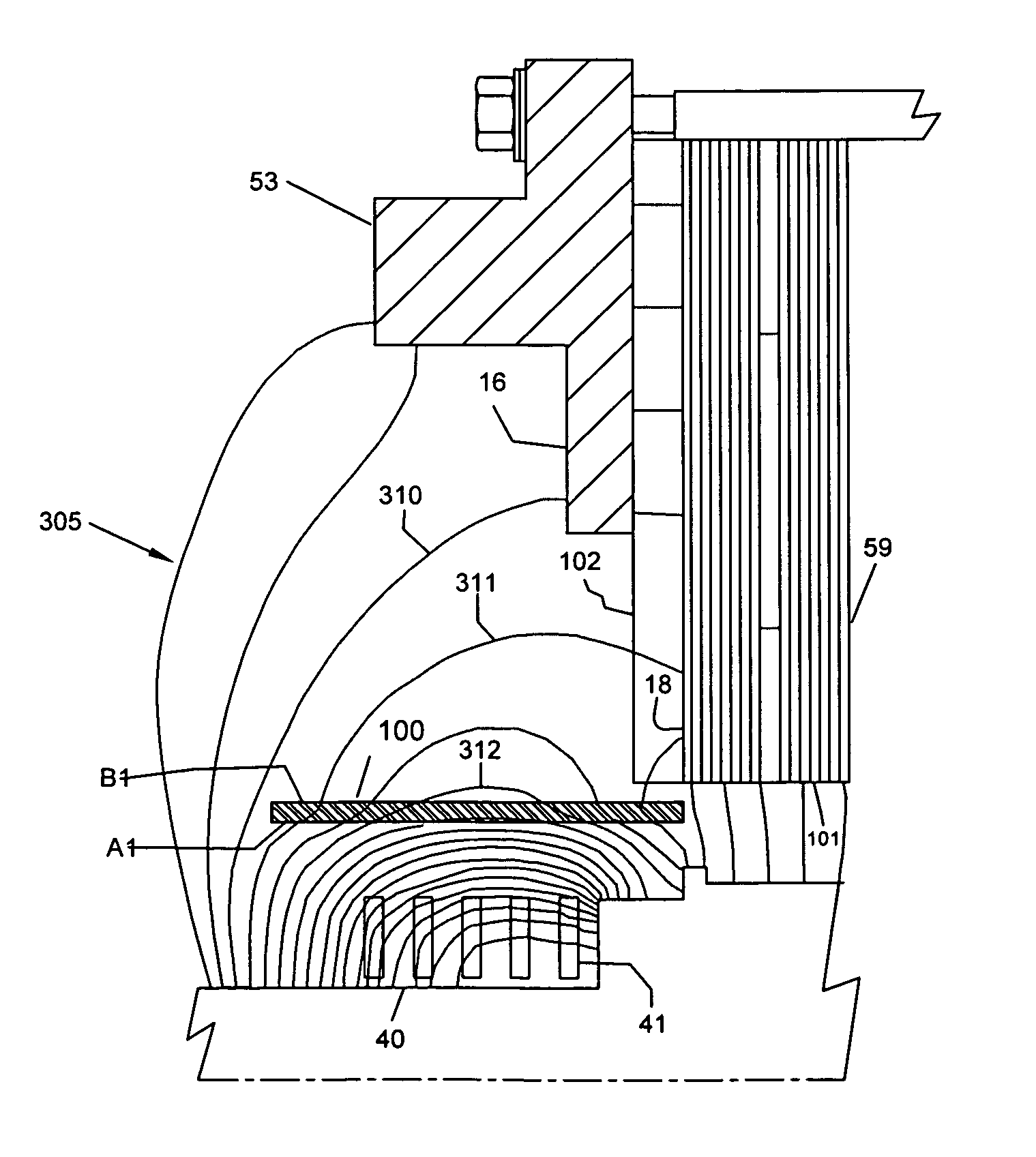
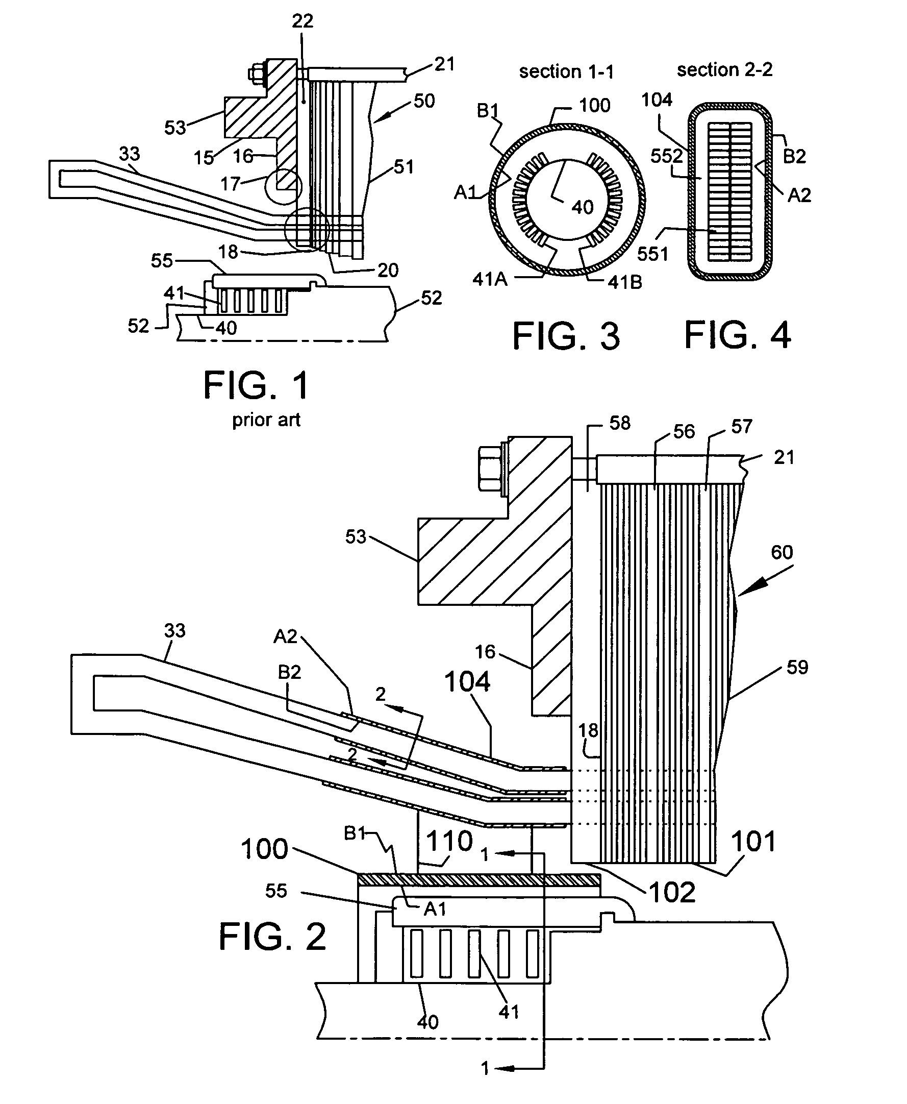
[0030]FIG. 2 shows the core-end 60 with a first flux-shield 100 on rotating flux source 41 and a second flux shield 104 on stationary flux source 33 in accordance with the present invention. The goal of the flux shields 100, 104 is to ensure that only a fraction of the flux produced by respective flux sources is received by any of the multiple flux receivers. The end-lamination packages 101, 59 in the core end 60 are identical to those used in the main body of the generator. That is, generators in accordance with the present invention do not have and end-stepped laminations, thereby saving on cost. The end-lamination packages 101, 59 are cooled by outer vent duct 58 and inner vent ducts 56, 57 as in conventional generators. But the outer vent spacer 58 extends all the way up to the bore 102 of the core, thereby strengthening the support to the tooth tips and stator bars, preventing their rattling and breakdown.

[0031]FIG. 3 is a sectional view at 1-1 showing the cross-section of the ...


PUM


Abstract

The invention provides for flux-shields wrapped around the flux-sources at the core-end of large power generators. They prevent overheating of all core-end parts under all abnormal conditions of operation. A first flux-shield is an electrically conductive cylindrical shell concentric with rotating end-windings, held outside the retaining ring. The rotating flux source induces eddy currents in the first flux-shield whose flux repels the source flux. Only a small part of the rotating source flux is hence received by all the core-end parts, thereby greatly reducing their temperatures. A second flux-shield comprises an electrically conductive tape wrapped over the ground-insulation of stator bars protruding from the core. Alternating flux generated by the stator bars induces eddy currents in the second flux-shield whose flux repels the source flux. Only a small fraction of the source flux is hence received by all core-end parts, thereby greatly reducing their temperatures. The present invention replaces multiple devices such as step-iron, flux-shields, flux shunts, short-rotors etc, used in the prior-art with only two devices. As a result, the design of the core-end is simplified and the cost of the generator is reduced.

Description

FIELD OF THE INVENTION[0001]This invention relates to large electric power generators, particularly to devices that prevent overheating of multiple components in the core-end.BACKGROUND OF THE INVENTION[0002]It is well known that the core-ends of large generators have two flux-sources (i.e., current carrying conductors)—an end-winding carrying direct currents in the rotor and an end-winding carrying alternating currents in the stator. It also has a large number of flux-receivers (i.e., conductive components that can carry induced currents)—stepped end-laminations, flanges, clamp bars, keybars, vent duct spacers, vent support sheets, retaining rings, centering disks, rotating shaft etc. The two flux sources radiate a fringe-flux field that rotates at synchronous speed. This fringe flux impinges large conductive surfaces of all flux-receivers, inducing large eddy currents in them. Further, in different abnormal conditions of operation, the fringe flux concentrates at different locatio...

Claims


Application Information

Patent Timeline
IPC IPC(8): H02K3/46
CPCH02K3/42
Inventor RAO, DANTAM K.
Owner RAO DANTAM K
Why Eureka
Try Eureka