Reconfigurable portable locator employing multiple sensor array having flexible nested orthogonal antennas

a portable locator and multiple sensor technology, applied in the field of walkover locator apparatus, can solve the problems of affecting the comfort and convenience of residents, affecting so as to improve the accuracy of locators, improve the manufacturability, and improve the measurement of horizontal magnetic field asymmetry

Inactive Publication Date: 2012-06-19
SEEK TECH
View PDF13 Cites 56 Cited by
  • Summary
  • Abstract
  • Description
  • Claims
  • Application Information

AI Technical Summary

Benefits of technology

[0015]This invention addresses the above unresolved problems by introducing for the first time a locator with a number of substantially identical sensor components to provide an orthogonal three-dimensional (3D) sensor array having a common sensor centroid that senses the three orthogonal emission field components at a single point using individual sensors that provide closely matched amplitude and frequency sensitivity over a 500 kHz frequency band, thereby improving locator accuracy. The identical flexible nested sensors of this invention are unexpectedly useful for improved manufacturability because only one set of component designs is required for the three individual sensors in a 3D sensor array of this invention. This invention also addresses the above unresolved problems by introducing for the first time a locator with multiple sensor redundancy in combination with improved measurement of the horizontal magnetic field asymmetry and improved user interface (UI) integration. This invention arises in part from the unexpectedly advantageous observation that two additional horizontally-spaced one-dimensional (1D) sensors may be simultaneously operated to produce reliable horizontal field asymmetry measurements without materially disturbing the 3D field vector measurements provided by two vertically-spaced 3D sensor arrays. Such horizontal field asymmetries are unexpectedly useful primarily because the locator user may use them to reorient the locator assembly azimuthally with respect to the buried utility line and thereby optimize the signal-to-noise ratio (SNR) for field vector measurements from the 1D sensor array to provide a left-right directional indication therefrom after the user orients the 1D sensor axis orthogonal to the buried utility line axis responsive to 3D array signals. This invention also addresses the above unresolved problems by introducing for the first time a locator with a user-configurable UI that provides software and UI elements that allow the user to specify the complexity and sophistication of the UI, thereby improving usability of the invention for a wide spectrum of users, from novice to one highly practiced in the art of location. This invention arises in part from the unexpectedly advantageous observation that a single multipurpose UI may include additional commands and controls for adding and removing command menu components and buried object location indicators under user control without affecting locator performance or accuracy.
[0016]It is a purpose of this invention to provide improved manufacturability through the introduction of a flexible sensor for use in the 3D sensor array of this invention with improved sensor accuracy and uniformity. It is a feature of this invention that the 3D sensor array employs three substantially-identical electromagnetic (EM) field sensors disposed in substantial concentricity such that the corresponding sensing axes are disposed in substantial mutual orthogonality.
[0017]It is another purpose of this invention to provide improved usability through independent magnetic field measurements sufficient for obtaining accurate buried object location indicators without undue experimentation and retrial by the user. It is a feature of this invention that, for optimal horizontal field asymmetry measurements, the two independent horizontally-spaced 1D sensors may be oriented orthogonally to a buried utility line by the user, thereby producing location indicators of unprecedented accuracy from the 3D sensor arrays.
[0018]It is yet another purpose of this invention to provide improved usability through the introduction of a user-configurable UI that permits a user to reconfigure the locator UI to a level of complexity no more than appropriate for the locator task at hand. It is a feature of this invention that the UI includes controls for adding and removing menu items and operating frequency bands under user control.

Problems solved by technology

If excavation equipment such as a backhoe hits a high voltage line or a gas line, serious injury and property damage may result.
Unintended severing of water mains and sewer lines generally leads to messy and expensive cleanup efforts.
The unintended destruction of power and data cables may seriously disrupt the comfort and convenience of residents and bring huge financial costs to business.
Also, many sites are host to a variety of overhead power and related lines, which emit electromagnetic fields that cannot be readily segregated from the emissions of similar buried lines.
Some transmitters known in the art can produce several different signals at different frequencies for application to the same underground object or even to different underground objects, but a problem with these systems arises when several pipes are located in the same area and the location of all pipes is desired.
Signals transmitted by several pipes can interfere and complicate the detection process.
Ng's nested printed-circuit board (PCB) supported coil structures appear to be relatively bulky and of too few turns for useful sensitivity in the lower frequency regions.
Although Ng's design permits the coils to be made nearly identical, the intersected regions in each coil are not symmetric, which introduces an orientation-specific non-uniform response to the field sensitivity over the operating frequency region.
The device disclosed by Motazed et al. appears to be relatively heavy and costly to fabricate and may exhibit a number of complex circuit resonances at high frequencies and a relatively narrow operating frequency region.
Ferrite cores also exhibit disadvantageous sensitivity to changes in operating temperature because ferrite permeability varies markedly with operating temperature.
Similarly, modern utility line tracing places complex demands on the locator user, who may be obliged to detect one or more buried objects in a crowded or electromagnetically noisy environment.
Effective detection and tracing of utility lines is vital to the safety of field personnel for many reasons; for example, the unplanned rupture of a high-pressure natural gas line can endanger the lives of everybody in the vicinity.
Another well-known problem with portable locator usability well-known in the art is the problem of the “quality” of a location indication.
This usability problem may result in false positives and other errors (e.g., errors in depth measurement) in locating underground utility lines, for example.
Such errors may result in unnecessary loss of user efficiency and safety.
Moreover, the utility of such a combination is apparently counterintuitive in the art because (a) the improved usability of measuring the horizontal B-field gradient separately from the two displaced 3D B-field vectors was unknown in the art until now; (b) the additional sensor channels necessary for adding a separate horizontal gradiometer significantly increase locator system cost with no apparent performance advantages; and (c) locating additional sensor coils near the existing locator sensor arrays introduces mutual inductance couplings that are known to reduce the accuracy of the locator system.

Method used


Image

  • Reconfigurable portable locator employing multiple sensor array having flexible nested orthogonal antennas
  • Reconfigurable portable locator employing multiple sensor array having flexible nested orthogonal antennas
  • Reconfigurable portable locator employing multiple sensor array having flexible nested orthogonal antennas

Examples


Embodiment Construction

[0041]The Elongated Sensor Assembly

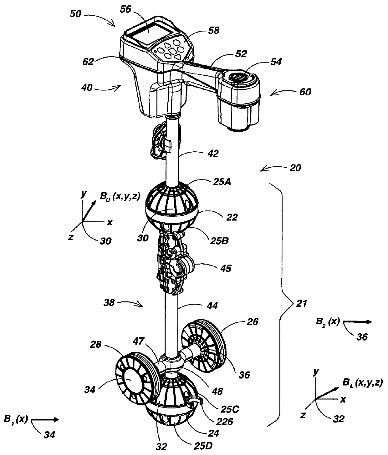
[0042]FIG. 1 is a perspective view illustrating a preferred embodiment 20 of the locator system of this invention shown in an operational configuration. Locator system 20 includes an elongated sensor assembly 21 having a first pair of electromagnetic (EM) sensor arrays 22 and 24 that are vertically spaced-apart and a second pair of EM sensors 26 and 28 that are horizontally spaced-apart and disposed to form a horizontal gradient sensor pair between sensor arrays 22 and 24 during operation. Upper and lower sensor arrays 22 and 24 each are enclosed within generally hemispherical top and bottom molded plastic shells in a watertight manner. Upper sensor array 22 is enclosed by a top shell 25A and a bottom shell 25B and lower sensor array 22 is enclosed by a top shell 25C and a bottom shell 25D. The seam between top shell 25A and bottom shell 25B is sealed with two layers of tape (not shown), which preferably includes application of a narrow inner taped...


PUM


Abstract

A portable locator for detecting a buried object characterized by an electromagnetic (EM) field emission employing three-dimensional (3D) sensor arrays each having three substantially-identical EM field sensors disposed on a flexible annular wall having a radial centroid defining a sensing axis. The flexible annular sensors are retained in substantial concentricity with the corresponding sensing axes disposed in substantial mutual orthogonality. A pair of 3D sensor arrays disposed on a first axis substantially orthogonal to a second axis defied by another pair of EM field sensors each having a sensing axis disposed along the second axis. The locator introduces a user-reconfigurable user interface (UI) employing a “sticky” ratcheting audio UI and a hollow hinge assembly for redisposing the sensor assembly from an operating to a storage disposition.

Description

CROSS-REFERENCES TO RELATED APPLICATIONS[0001]This application is related by common inventorship and subject matter to the commonly-assigned patent application Ser. No. 10 / 268,641, published on Apr. 15, 2004 as U.S. Patent Application No. 2004 / 0070399 A1, now U.S. Pat. No. 7,009,399 granted Mar. 7, 2006, and to the commonly-assigned patent application Ser. No. 10 / 308,752, published on Apr. 15, 2004 as U.S. Patent Application No. 2004 / 0070525 A1, now abandoned, which are both entirely incorporated herein by this reference. This application is also related by common inventorship and subject matter to the commonly-assigned patent application Ser. No. 10 / 956,328 filed on Oct. 1, 2004, the commonly-assigned patent application Ser. No. 11 / 054,776 filed on Feb. 9, 2005, which was abandoned in favor of U.S. patent application Ser. No. 11 / 205,267, now U.S. Pat. No. 7,136,765 granted Nov. 14, 2006, the commonly-assigned patent application Ser. No. 11 / 106,894 filed on Apr. 15, 2005, and the co...

Claims


Application Information

Patent Timeline
Patent Type & Authority Patents(United States)
IPC IPC(8): G01V3/11G01V3/08
CPCG01V3/15G01V3/165G01V11/00G01V3/12
Inventor OLSSON, MARK S.STUART, PAUL G.COX, DAVID A.MEREWETHER, RAYSHAFFER, DAWN E.LEVIN, RYAN B.MARTIN, MICHAEL J.
Owner SEEK TECH
Why Eureka
Try Eureka