Image processing apparatus and image processing method

a technology of image processing and image processing equipment, which is applied in the direction of color signal processing circuits, instruments, television systems, etc., can solve the problems of data transmission bandwidth bottlenecks, difficult to expand data transmission bandwidth as much, and increase costs, so as to achieve the effect of suppressing the occurren

Inactive Publication Date: 2012-06-19
CANON KK
View PDF17 Cites 1 Cited by
  • Summary
  • Abstract
  • Description
  • Claims
  • Application Information

AI Technical Summary

Benefits of technology

[0010]An embodiment of the present invention provides a technology that suppresses the occurrence of situations where generation of image data representing high-quality images is impossible even if the data transmission bandwidth of the frame memory of the image processing apparatus is relatively limited.

Problems solved by technology

However, it is difficult to expand the data transmission bandwidth as much as one might want to because the expansion of the data transmission bandwidth of the frame memory brings about a cost increase.
As a result, situations arise, in which the data transmission bandwidth creates a bottleneck and image data representing high-quality images cannot be generated.

Method used


Image

  • Image processing apparatus and image processing method
  • Image processing apparatus and image processing method
  • Image processing apparatus and image processing method

Examples


first embodiment

10>

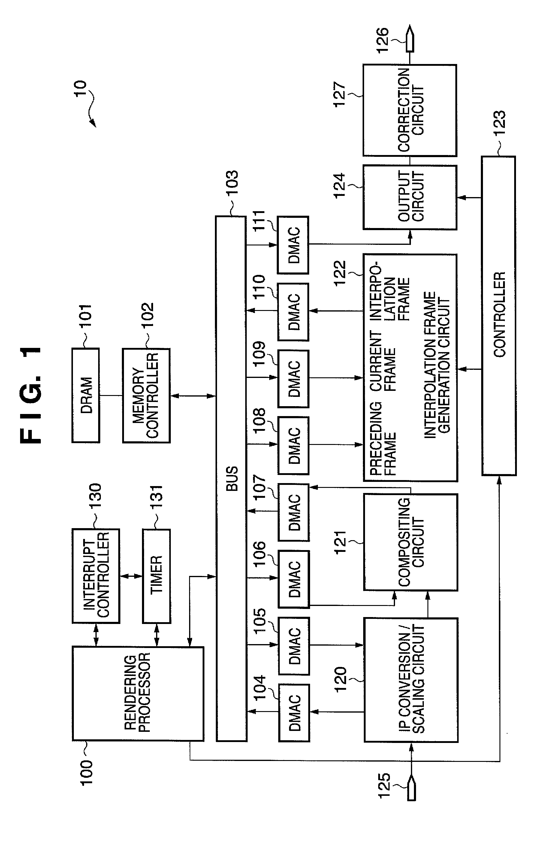
[0058]FIG. 1 is a diagram illustrating the configuration of an image processing apparatus 10 according to a first embodiment utilizing the technology of the present invention.

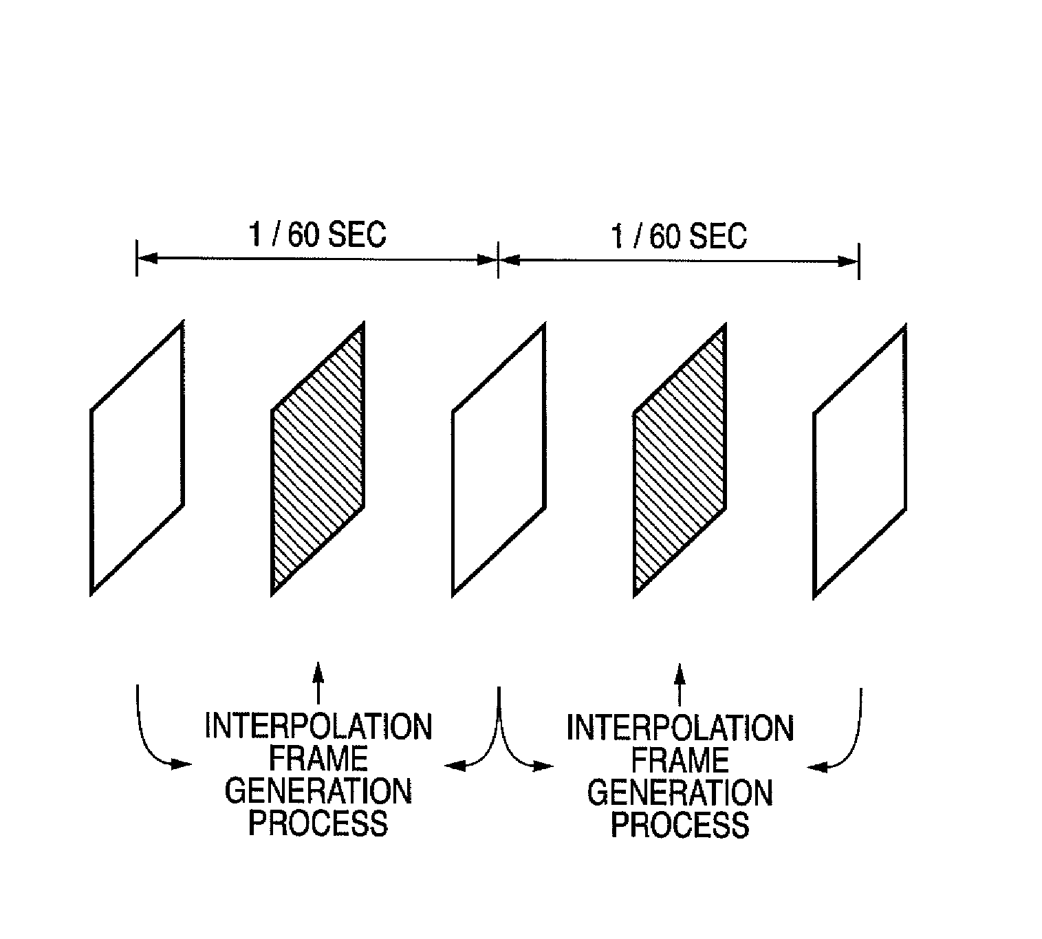
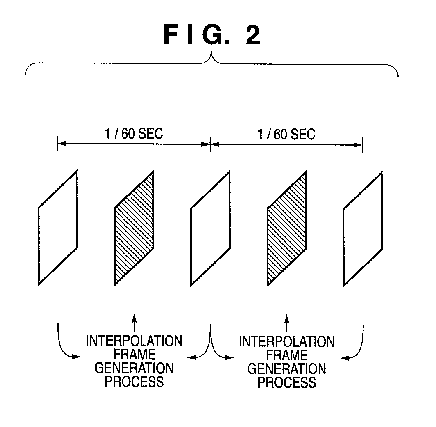
[0059]The image processing apparatus 10 includes a rendering processor 100, which is an example of a generating unit, and an interpolation frame generation circuit 122, which is an example of an interpolating unit. The rendering processor 100 renders (generates) the image data that is composited with (each piece of frame data of) the video data. The interpolation frame generation circuit 122 generates interpolation frame data that is inserted between the frame data. The interpolation frame data is used for changing (especially, accelerating) the frame rate. Any suitable technology, such as, for instance, the one described in Japanese Patent Laid-Open No. 10-191268, can be used to generate interpolation frame data.

[0060]The reference numeral 101 designates a DRAM, which is a memory used as a frame memory for ...

second embodiment

[0119]The image processing apparatus 10 according to the first embodiment completely stopped the generation of interpolation frame data when predetermined conditions were met.

[0120]Incidentally, menu screens and other composite images are often represented by still images or by animation images having a low frame rate. In such cases, generating interpolation frame data corresponding to the composite image areas in the original frames does not particularly improve the image quality of the composite images. This is due to the fact that, in many cases, the composite images do not change between the two original frames, on which the generation of interpolation frame data is based.

[0121]Accordingly, in the second embodiment, when the rendering processor 100 generates image data, the generation of interpolation frame data is halted only in those areas of the original frames where image data is composited. In areas other than those areas, the generation of interpolation frame data continue...

third embodiment

[0154]In a third embodiment, each portion of image data has a blending coefficient “α”. The blending coefficient “α” is a parameter that indicates the degree of transparency obtained when compositing image data with video images, in such a manner that the smaller the “α” is, the higher the degree of transparency of the image data becomes. In the present embodiment, interpolation frame data used for the compositing area is generated when the “α” is not more than a threshold value, i.e. when the image data is composited such that the degree of transparency is equal to, or greater than, a predetermined degree. Conversely, no interpolation frame data is generated when the “α” is more than the threshold value, with the frame rate of the compositing area accelerated based on the frame doubling scheme. Alternatively, priority is given to image data with a larger “α” (a low degree of transparency) and the frame doubling scheme is used as the frame rate conversion scheme in the compositing a...


PUM


Abstract

An apparatus includes a memory which successively stores frame data of video data, an interpolating unit which generates interpolation frame data which is inserted between the frame data and stores the interpolation frame data in the memory, and a readout unit which successively reads out the frame data and the interpolation frame data from the memory at a frame rate higher than a frame rate of the video data. The apparatus further includes a generating unit which generates image data which is composited with the frame data and stores the image data in the memory, and a control unit which, based on display-related characteristics of the image data, controls the interpolating unit to halt the generation of the interpolation frame data, and also controls the readout unit to read out the frame data in duplicate instead of the interpolation frame data.

Description

BACKGROUND OF THE INVENTION[0001]1. Field of the Invention[0002]The present invention relates to an image processing apparatus and an image processing method that accelerate the frame rate of video data.[0003]2. Description of the Related Art[0004]There are at present time well-known techniques for accelerating the frame rate of video data (see Japanese Patent Laid-Open No. 10-191268). In accordance with the technique of Japanese Patent Laid-Open No. 10-191268, a video signal having 50 frames per second is converted to 100 frames per second using field interpolation.[0005]Furthermore, it is also known to display menu screens and other images (computer graphics) by compositing them with video images, with images of increasingly higher quality (e.g. high-definition animation images, etc.) being composited in recent years. A display device including circuitry that generates computer graphics signals is disclosed in Japanese Patent Laid-Open No. 2000-181440.[0006]When interpolation fram...

Claims


Application Information

Patent Timeline
Patent Type & Authority Patents(United States)
IPC IPC(8): H04N7/01H04N11/20
CPCH04N7/0132H04N7/0135
Inventor SAGA, YOSHIHIRO
Owner CANON KK
Why Eureka
Try Eureka