Complex inductor and power supply unit

a technology of inductor and power supply unit, which is applied in the direction of electric variable regulation, process and machine control, instruments, etc., can solve the problems of high cost of converters, and achieve the effects of compact power supply, high efficiency and low cos

Inactive Publication Date: 2012-06-19
HITACHI INFORMATION & TELECOMM ENG LTD
View PDF15 Cites 6 Cited by
  • Summary
  • Abstract
  • Description
  • Claims
  • Application Information

AI Technical Summary

Benefits of technology

[0016]Another object of the present invention is to provide a compact, highly efficient, inexpensive power supply unit by using the complex inductor according to the present invention.
[0020]A power supply unit in another preferred mode of the present invention uses the inventive complex inductor as a smoothing inductor and resonant inductor of so that circulating currents flowing in the resonant inductor and transformer winding are reduced while a smoothing inductor in an insulated DC-DC converter release energy, making the power supply compact, highly efficient, and inexpensive.

Problems solved by technology

The conventional DC-DC converter disclosed in Non-patent Document 1 needs a free-wheeling diode to reduce the circulating current, making the converter expensive.

Method used


Image

  • Complex inductor and power supply unit
  • Complex inductor and power supply unit
  • Complex inductor and power supply unit

Examples


first embodiment

[0033][First Embodiment]

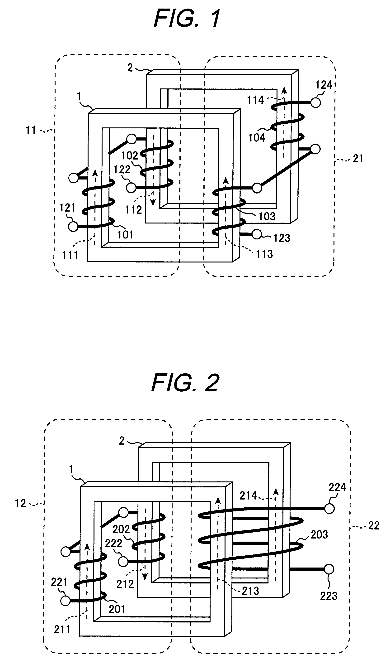
[0034]FIG. 1 shows the structure of a complex inductor in a first embodiment of the present invention. The complex inductor, shown in FIG. 1, in the first embodiment includes a magnetic member 1 forming a first closed magnetic path and a magnetic member 2 forming a second closed magnetic path. Windings 101 and 103 are formed around the magnetic member 1, and windings 102 and 104 are formed around the magnetic member 2. One end of the winding 103 is connected to one end of the winding 104. The other end of winding 103 is a terminal 123, and the other end of the winding 104 is a terminal 124. A part between the terminals 123 and 124 is an inductor 21. The windings 101 and 102 are mutually connected in a direction in which, when a current flowing in the inductor 21 is changed, the resulting induced voltage in the winding 101 and the resulting induced voltage in the winding 102 weaken each other. The other end of the winding 101 is a terminal 121, and the other e...

second embodiment

[0050][Second Embodiment]

[0051]A complex inductor in a second embodiment according to the present invention will be described below with reference to FIG. 2. FIG. 2 shows the structure of a complex inductor in the second embodiment of the present invention. The complex inductor, shown in FIG. 2, in the second embodiment includes a magnetic member 1 forming a first closed magnetic path and a magnetic member 2 forming a second closed magnetic path. A winding 201 is formed around the magnetic member 1, and winding 202 is formed around the magnetic member 2. A winding 203 is formed in such a way that the magnetic members 1 and 2 are bound together. One end of the winding 201 is connected to one end of the winding 202 so that a magnetic flux generated by a current flowing in the winding 201 and a magnetic flux generated by a current flowing in the winding 202 are cross-linked in a reverse direction with respect to the winding 203. The other end of winding 201 is a terminal 221, and the o...

third embodiment

[0054][Third Embodiment]

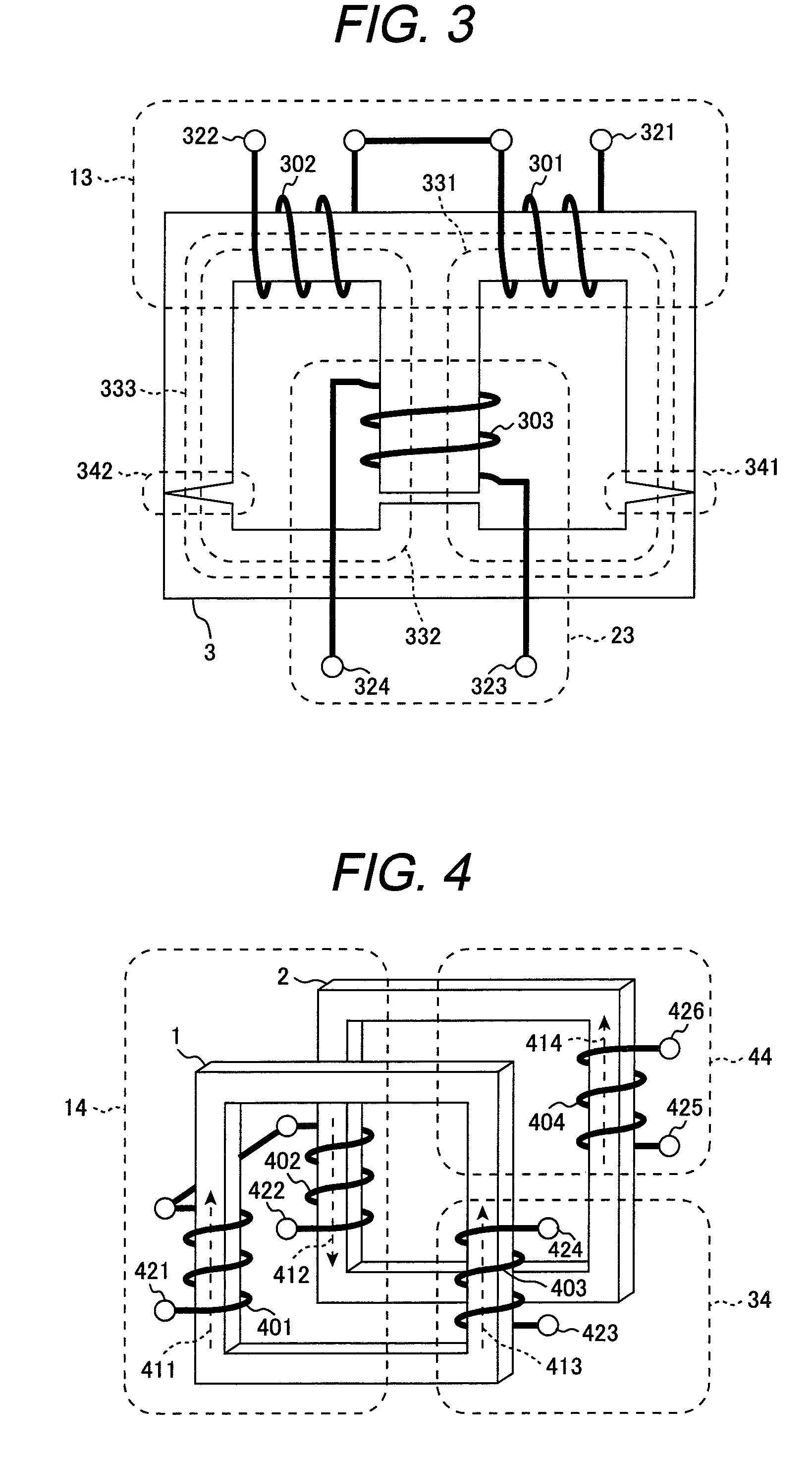
[0055]FIG. 3 shows the structure of a complex inductor in a third embodiment of the present invention. The complex inductor, shown in FIG. 3, in the third embodiment includes a magnetic member 3 forming closed magnetic paths 331, 332, and 333. A winding 301 is formed around a part shared by the closed magnetic paths 331 and 333, a winding 302 is formed around a part shared by the closed magnetic paths 332 and 333, and a winding 303 is formed around a part shared by the closed magnetic paths 331 and 332. Both ends of the winding 303 are terminals 323 and 324. A part between the terminals 323 and 324 is an inductor 23. One end of the winding 301 is connected to one end of the winding 302 in a direction in which an induced voltage generated by a current flowing in the inductor 23 in the winding 301 and an induced voltage in the winding 302 weaken each other. The other end of the winding 301 is a terminal 321, and the other end of the winding 302 is a terminal 32...


PUM


Abstract

A complex inductor according to the present invention changes its magnetic coupling polarity according to currents flowing its two inductors. The complex inductor includes a first magnetic member, around which first and third windings are formed, and a second magnetic member, around which second and fourth windings are formed. A first inductor is formed by connecting the first winding to the second winding, and a second inductor is formed by connecting the third winding to the fourth winding. The two magnetic members are made of a magnetic material having a magnetic permeability that gradually decreases as its magnetic flux density is increased. When the two windings are interconnected in a direction in which induced voltages generated in these windings by the current flowing in the second inductor weaken each other, the magnetic coupling polarity between the first and second inductors changes according to the current flowing in the inductors. The two inductors are magnetically coupled so that, when one of the two inductors stores energy, the current flowing in the other inductor increases, and when one of the two inductors releases energy, the current flowing in the other inductor decreases.

Description

CLAIM OF PRIORITY[0001]The present application claims priority from Japanese patent application serial No. 2007-320221, filed on Dec. 11, 2007, the content of which is hereby incorporated by reference into this application.FIELD OF THE INVENTION[0002]The present invention relates to a complex inductor (reactor) that is used in a power supply circuit or the like and to a power supply unit.BACKGROUND OF THE INVENTION[0003]As recent electronic units become compact, highly efficient, and inexpensive, power supply units are also required to be compact, highly efficient, and inexpensive. Patent Document 1 below discloses two inductors that share part of a magnetic loop to reduce their costs. In Patent Document 1, a single core member is used to provide two inductors that are magnetically independent of each other.[0004]Patent Document 2 below discloses a resonant reactor and a smoothing reactor that are structured by forming a plurality of windings around a plurality of closed magnetic pa...

Claims


Application Information

Patent Timeline
Patent Type & Authority Patents(United States)
IPC IPC(8): H02M3/335
CPCH01F27/38H01F38/02H02M3/337H01F17/04H01F37/00H01F2038/026Y02B70/1433Y02B70/10H02M3/33573H02M3/01H02M1/14
Inventor SHIMADA, TAKAETANIGUCHI, KIMIAKISHOJI, HIROYUKI
Owner HITACHI INFORMATION & TELECOMM ENG LTD
Why Eureka
Try Eureka