Method and arrangement to reverse the power flow of a direct current power transmission system

a technology of direct current and power transmission system, which is applied in the direction of circuit arrangement, power conversion system, electric power transfer ac network, etc., can solve the problems of harmonic current generation and reactive power consumption, and achieve the effects of reducing direct voltage, reducing costs, and reducing stress on dc cables

Active Publication Date: 2012-06-19
HITACHI ENERGY SWITZERLAND AG
View PDF5 Cites 3 Cited by
  • Summary
  • Abstract
  • Description
  • Claims
  • Application Information

AI Technical Summary

Benefits of technology

[0011]A power reversal is achieved by changing the operation modes in the converters from rectifier to inverter and vice versa and by reversing the direct voltage. Typically, a power reversal is achieved by reducing the direct current in order to decrease the active power, followed by a temporary block of the converters at minimum power and a restart of the converters with newly adjusted delay angles α. The operation at low direct current is disadvantageous since it results in reduced reactive power consumption in the converters which may lead to increased reactive power generation to the AC system.
[0034]In a still further embodiment, the first control unit additionally controls a transformer with on-load tap changers on the AC side of the first station and / or the second control unit additionally controls a transformer with on-load tap changer on the AC side of the second station. The power reversal methods known in the art often require to step the tap changers multiple times during power reversal. If frequent power reversal occurs, the frequent stepping of the tap changers leads to an increased necessity of maintenance. With the inventive method and arrangement, the number of tap changer steps during power reversal is reduced, preferably to zero, which reduces the wear and tear of the tap changers. Therefore it is a feature of the still further embodiment that a tap changer control function in the first and / or the second station is blocked before power reversal and released after power reversal. In an extension of this embodiment the tap changer control function in the first and / or the second station is blocked except for tap changer steps to reduce the valve stresses. Even though a limited number of tap changer steps is now allowed, it still helps to reduce the total number of tap changer steps performed during power reduction from nominal to minimum power from about 6 to 8 down to 1 to 2 steps.

Problems solved by technology

Each converter, no matter if in rectifier or inverter operation mode, generates harmonic currents and consumes reactive power, basically due to switching of the thyristor valves.

Method used


Image

  • Method and arrangement to reverse the power flow of a direct current power transmission system
  • Method and arrangement to reverse the power flow of a direct current power transmission system
  • Method and arrangement to reverse the power flow of a direct current power transmission system

Examples


Embodiment Construction

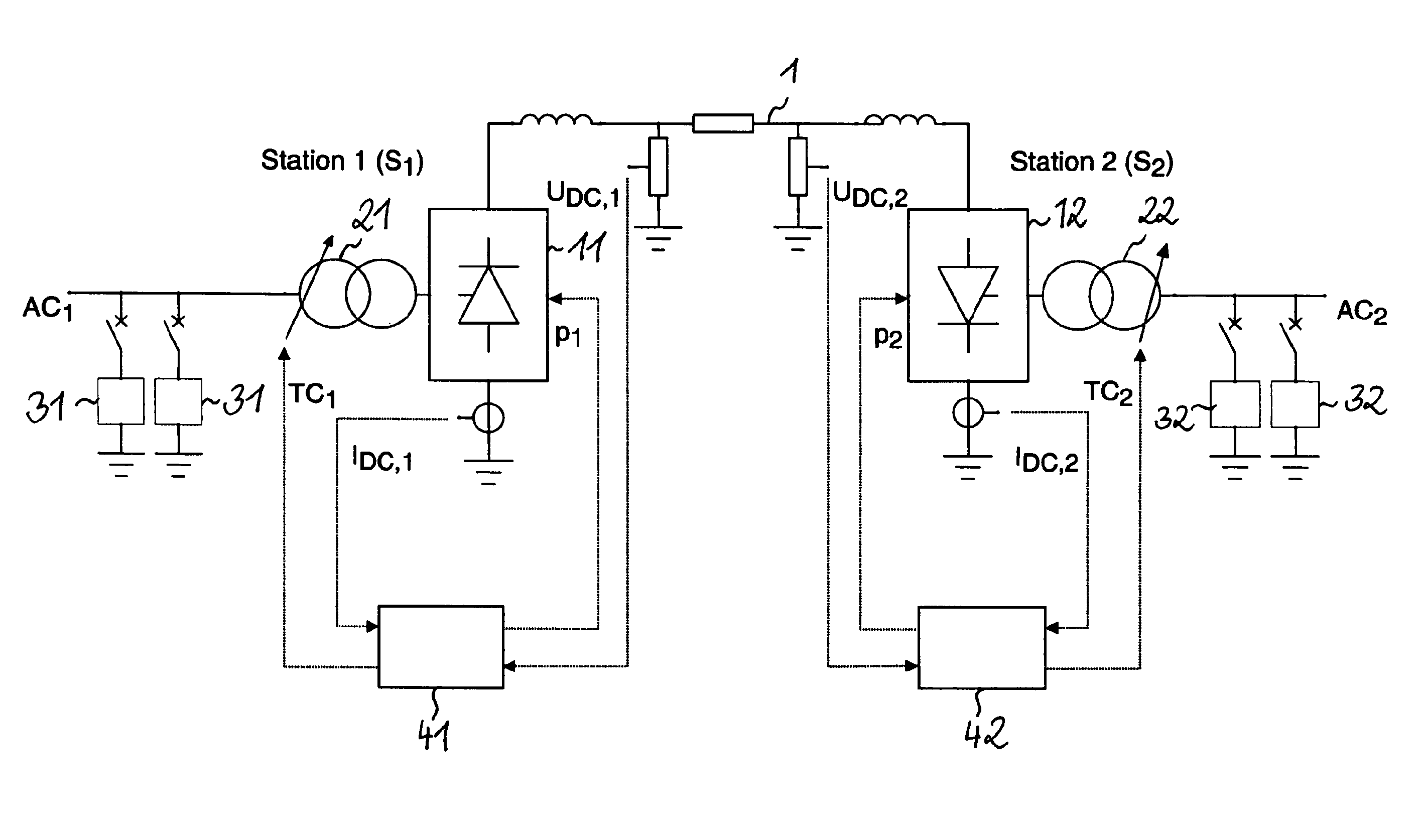
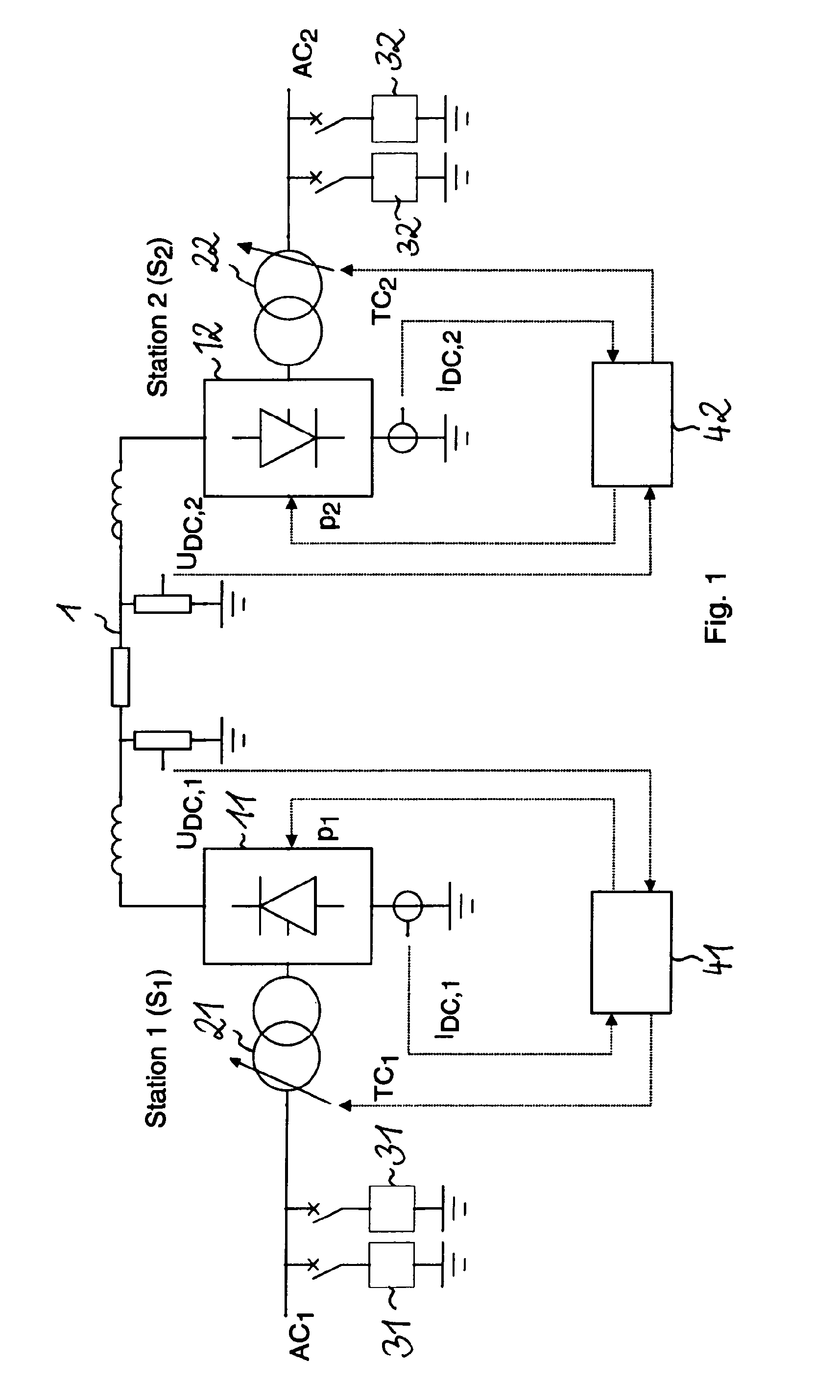
[0040]In FIG. 1 a direct current power transmission system is shown which comprises a first converter station S1 and a second converter station S2. The converter stations S1 and S2 are coupled to each other via a direct current link 1. The direct current power transmission system is used to transfer active power P between a first alternative current power system AC1 and a second alternative current power system AC2.

[0041]Each of the converter stations S1 and S2 contains a line commutated converter 11 or 12, a transformer 21 or 22 with an on-load tap changer as well as elements for reactive power consumption which in this example are AC filters 31 and 32. The operation of the converter 11 and of the tap changer of the first converter station S1 is controlled via a first control unit 41. And the operation of the converter 12 and of the tap changer of the second converter station S2 is controlled via a second control unit 42. The first and the second control units 41 and 42 each receiv...


PUM


Abstract

A direct current power transmission system includes a first and a second converter station that are coupled to each other via a direct current link. Each converter station includes a first or second line commutated converter, respectively. Before power reversal the first converter is operated as a rectifier and the direct current is controlled in the first station, while the second converter is operated as an inverter and in the second station the extinction angle of the second converter or the direct voltage is controlled. After power reversal, the first converter is operated as an inverter and the second converter as a rectifier. During power reversal a change is carried out in the first station from control of the direct current to control of the extinction angle of the first converter or to control of the direct voltage, which is performed in synchronization with a change in the second station from control of the extinction angle of the second converter or from control of the direct voltage to control of the direct current.

Description

CROSS-REFERENCE TO RELATED APPLICATIONS[0001]This application is the national phase under 35 U.S.C. §371 of PCT / EP2007 / 052431 filed 15 Mar. 2008.FIELD OF THE INVENTION[0002]The invention relates to a method and an arrangement to reverse the power flow between a first and a second converter station which are coupled to each other via a direct current link, where each converter station comprises a first or second line commutated converter, respectively. Before power reversal, the first station is operated as rectifier and the direct current in the link is controlled in the first station, while the second station is operated as inverter and its extinction angle is controlled in the second station. After power reversal, the first station is operated as inverter and the second station as rectifier. The arrangement comprises a first control unit in the first station and a second control unit in the second station to perform the power reversal method.BACKGROUND OF THE INVENTION[0003]Direct...

Claims


Application Information

Patent Timeline
Patent Type & Authority Patents(United States)
IPC IPC(8): H02J3/36H02M5/458
CPCH02J3/36H02M7/7575Y02E60/60
Inventor RADBRANDT, ULF
Owner HITACHI ENERGY SWITZERLAND AG
Why Eureka
Try Eureka