Endoscope cutting and retrieving snare instrument

a technology for snare instruments and endoscopes, which is applied in the field of surgical instruments, can solve the problems of difficult capture of polyps and patient retrieval, frequent preventing visual inspection of patient internal tissues, and drawbacks of suction

a technology for snare instruments and endoscopes, which is applied in the field of surgical instruments, can solve the problems of difficult capture of polyps and patient retrieval, frequent preventing visual inspection of patient internal tissues, and drawbacks of suction

US8206401B2Active Publication Date: 2012-06-26GRANIT MEDICAL INNOVATION

Image

  • Endoscope cutting and retrieving snare instrument
  • Endoscope cutting and retrieving snare instrument
  • Endoscope cutting and retrieving snare instrument

Examples


Embodiment Construction

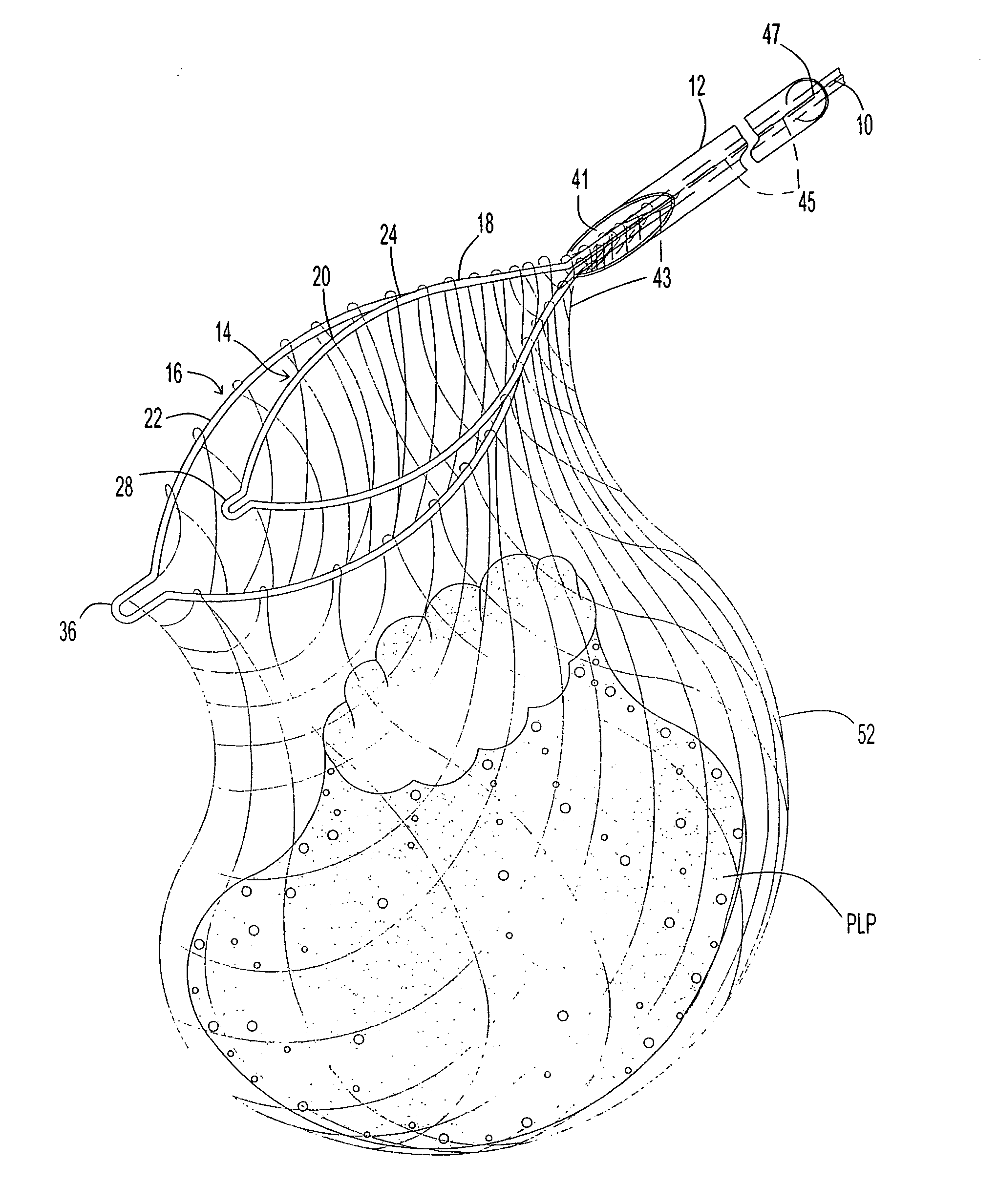
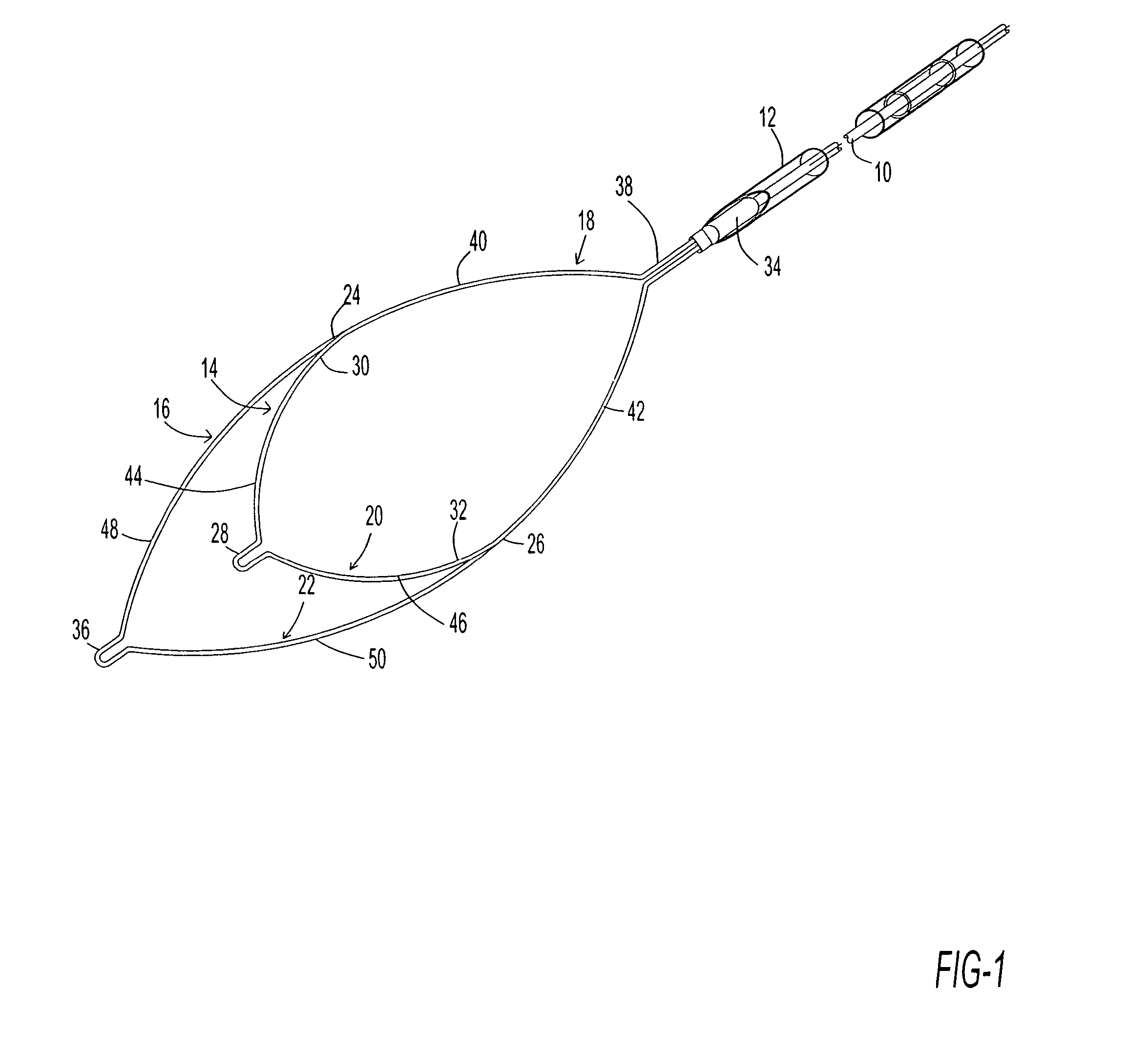
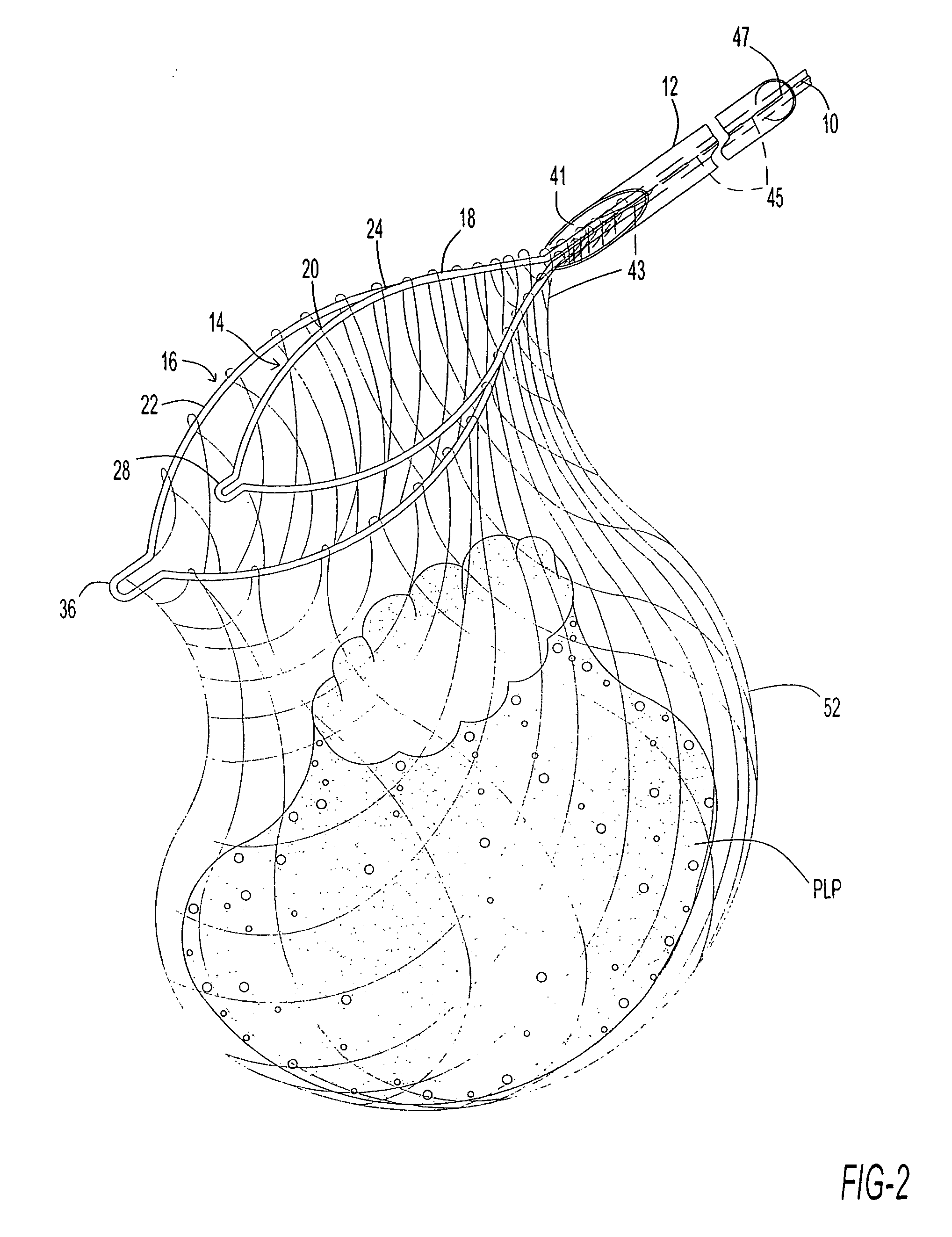
[0034]As depicted in FIG. 1, a surgical instrument for use in an endoscopic tissue resection procedure comprises an elongate electrically conductive slider member or pusher wire 10 movably extending through a tubular introducer member 12 such as a catheter. The catheter is dimensioned to fit down the biopsy channel of a flexible endoscope. The instrument of FIG. 1 additionally comprises an inner loop 14 and an outer loop 16 (collectively, an end effector) both operatively connected to a distal end of wire 10. Inner loop 14 and the outer loop 16 have a common proximal loop portion 18 and different distal loop portions 20 and 22. The distal loop portion 22 of outer loop 16 is longer than the distal loop portion 20 of inner loop 14 with the result that the outer loop is larger than the inner loop. Inner loop 14 and distal loop portion 22 of outer loop 16 each have a width, the largest width of distal loop portion 22 of outer loop 16 being at least as large as the largest width of inner...


PUM


Abstract

An endoscopic cutting and retrieval instrument includes an elongate electrically conductive wire and an inner loop and an outer loop both connected to a distal end of the wire. The inner loop and the outer loop have a common proximal loop portion and different distal loop portions. The distal loop portion of the outer loop is longer than the distal loop portion of the inner loop so that the outer loop is larger than the inner loop. A net attached to the outer loop forms a retrieval basket for capturing severed polyps and other tissues masses.

Description

BACKGROUND OF THE INVENTION[0001]This invention relates to a surgical instrument assembly for use in removing and retrieving selected tissues from internal body cavities of a patient. This invention more specifically relates to an instrument assembly for use in snare operations. The invention is particularly useful in the removal of polyps, for example, from the colon of a patient during an endoscopic procedure.[0002]In a conventional endoscopic snare operation, an endoscope is inserted into an internal cavity of a patient, e.g., into the colon, and is used to locate abnormal tissue growths such as polyps in the internal cavity. Upon the locating of a polyp or other growth which is to be removed, a wire extending through a tube in the biopsy channel of the endoscope is slid in the distal direction so that a cauterization loop connected to the wire is ejected from the distal end of the tube and the endoscope. The loop and the endoscope are manipulated from outside of the patient to p...

Claims


Application Information

Patent Timeline
26 Jun 2012
Publication
US8206401B2
IPC
A61B17/26
CPC
A61B17/221; A61B17/32056; A61B2017/00287; A61B2017/2212
Inventors
NAKAO, NAOMI L.