Aluminium foil alloy

a technology of aluminum foil and alloy, applied in the field of aluminum alloy products, can solve the problems of reducing casting productivity, difficult to roll the foil down to the final gauge, and containing alloys, and achieve good mechanical properties

Inactive Publication Date: 2012-06-26
EUROFOIL LUXEMBOURG
View PDF8 Cites 7 Cited by
  • Summary
  • Abstract
  • Description
  • Claims
  • Application Information

AI Technical Summary

Benefits of technology

[0019]It is an object of this invention to provide a new and economic method of manufacturing an aluminium alloy product, a method that leads to a combination of good mechanical properties in terms of the balance between strength and elongation in both longitudinal and transverse directions, which avoids the creation of blackening deposits during deep drawing operations and which provides wide processing windows for either a batch annealed or continuous annealed product.

Problems solved by technology

In a continuous casting process the higher Si containing alloys are considered to reduce casting productivity because centre line segregation effects become worse at higher casting speeds.
In producing thin foil products it is usually considered that the rolled product must not become too hard otherwise it becomes difficult to roll the foil down to final gauge.
A product, which is just cold rolled, would have high strength (due to the work hardening) but limited ductility.
However these grain structures are highly anisotropic.
Whilst there is a significant drop in strength from the as cold rolled state and an increase in ductility, the ductility may not reach the levels achieved in a partially recrystallized material.
However, since the temperatures for this are very high, the metal then enters a regime where the balance between the forces driving grain growth and grain boundary pinning is unstable and uncontrolled grain growth can appear suddenly.
Production routes where direct chill, (DC), casting is used are more complicated and expensive than continuous cast routes because they usually involve more processing steps, some of which are lengthy and energy intensive, such as homogenization.
But even with a continuous cast product to start with; reduction to final gauge usually involves an interannealing step, itself energy expensive and time consuming.
On the other hand if the YS is very close to the UTS an alloy product is not ideal for use in drawn containers.
In these alloys, where the ratio of Fe to Si is 1:1, the addition of Mn leads to an unstable annealing response at temperatures of 320° C. and above.

Method used


Image

  • Aluminium foil alloy
  • Aluminium foil alloy
  • Aluminium foil alloy

Examples


example 1

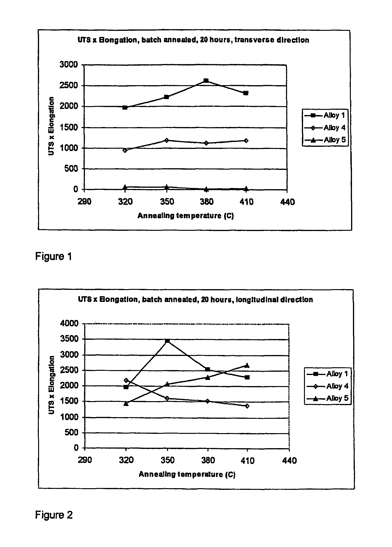
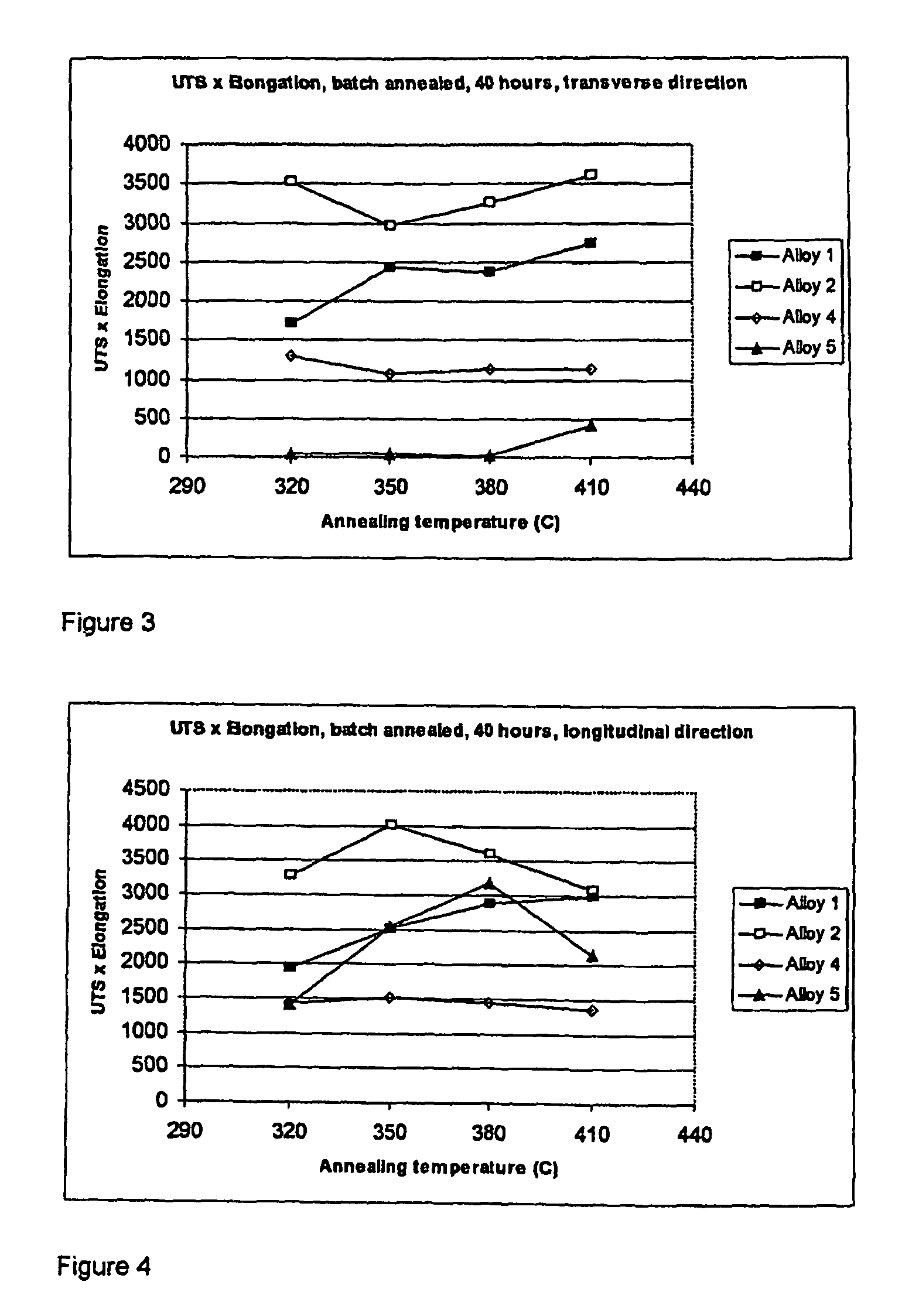
[0071]Table 1 summarises the alloy compositions investigated. Alloys 1 and 2 are alloys within the scope of the invention. Alloy 4 is an AA8011 type alloy with Fe towards the lower end of the composition range, i.e. similar to products commercially available, but with an addition of Mn. Alloy 5 is an alloy according to the prior art WO 03 / 069003. For each composition the other elements were <0.05 each and <0.15 in total with the balance Al.

[0072]All alloys were continuously cast in a twin roll caster to the gauges shown in Table 1. They were then cold rolled on a lab-scale cold mill to a final gauge of 150 μm without an interannealing step. Each cold rolled product of alloys 1, 4 and 5 was then subjected to batch annealing treatments at 320, 350, 380 and 410° C. for periods of 20, 40 and 60 hours. Alloy 2 was batch annealed at these temperatures for a duration of 45 hours. Alloy 5 in particular, was found to have very inconsistent mechanical properties due to a completely different ...

example 2

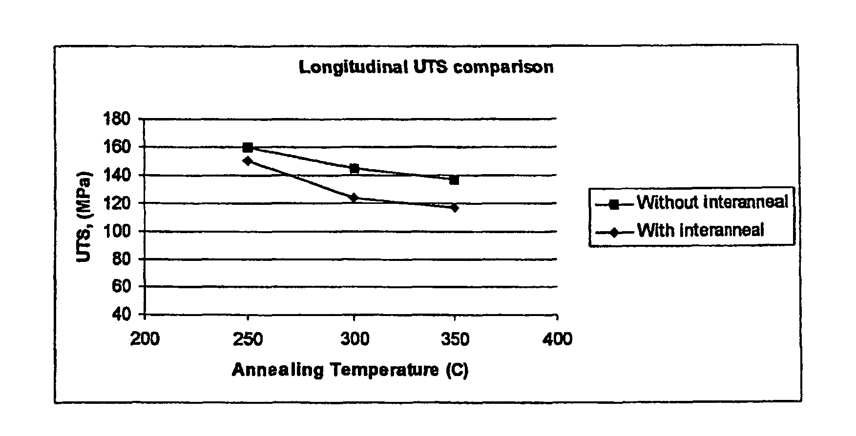
[0078]Alloy 1 was continuously cast in a twin roll caster to the same gauge as in Table 1 and then cold rolled on a lab-scale cold mill to a gauge of 1.5 mm. At this point, some samples were subject to an interanneal and others were not. For those interannealed, the heat up rate was 50° C. per hour and they were held at a temperature of 320° C. for 4 hours. They were then air-cooled. All samples were then cold rolled to a final gauge of 210 μm. Samples of the cold rolled product, with and without the interanneal, were subjected to four final batch annealing treatments. All the anneals were for a duration of 4 hours and at temperatures of 250, 300 and 350° C.

[0079]The processing route with an interanneal at 320° C. and the final anneal 300° C. reflects the recommended production route from WO 02 / 064848. The mechanical properties of alloy 1 after these treatments are given in Table 5 and FIGS. 8 to 13. They show there is a significant difference between the mechanical properties attai...

example 3

[0085]In order to demonstrate the typical level of properties achievable on an industrial scale and at different gauges, alloy 2 was continuously cast by twin roll casting to the same gauge as in Example 1 and cold rolled on an industrial cold mill to gauges of 78, and 116 μm without interanneals using conventional cold rolling pass schedules. The cold rolled product of gauge 78 μm was batch annealed at 350° C. for 25 hours and the 116 μm gauge product was annealed at 320° C. for 30 hours. The mechanical test results are shown in Table 7.

[0086]

TABLE 7Gauge (μm)TL78YS112110UTS138143E2324UTS × E31743432116YS125126UTS156158E28.930UTS × E4508.44740

[0087]Whilst Examples 1 and 2 illustrate the relative advantages of the inventive process as applied to alloys 1 and 2 over the prior art, this Example illustrates the kind of properties attainable in full industrial production.

[0088]Lab-scale cold rolling, as used in Examples 1 and 2, involves different thermal and strain conditions. In an in...


PUM

PropertyMeasurementUnit
temperatureaaaaaaaaaa

Abstract

The present invention relates to a method of making an aluminum alloy product having a gauge below 200 μm. It also relates to an aluminum alloy product having a gauge below the same value and to containers for food packaging application made from the aluminum alloy product. The invention is process of manufacturing an aluminum alloy comprising the following steps: continuous casting an aluminum alloy melt of the following composition, (in weight %): Fe 1.0-1.8, Si 0.3-0.8, Mn up to 0.25, other elements less than or equal to 0.05 each and less than or equal to 0.15 in total, balance aluminum, cold rolling the cast product without an interanneal step to a gauge below 200 μm and final annealing the cold rolled product.

Description

FIELD OF THE INVENTION[0001]The present invention relates to a method of making an aluminium alloy product having a gauge below 200 μm. It also relates to an aluminium alloy product having a gauge below the same value and to containers for food packaging applications made from this aluminium alloy product.RELATED ART[0002]Alloys of aluminium have been used for many years as a foil for household cooking purposes, food packaging and other applications. A series of alloy compositions have been developed for such uses and they include alloys based on the compositions AA8006, AA8011, AA8111, AA8014, AA8015, AA8021 and AA8079, (where these compositions are those designated by the internationally recognised standards of the Aluminum Association of America). Alloys of the 3XXX (series may also be used for foil applications, alloy AA3005 for example. Alloys of the AA8079 or AA8021 type have a high Fe content and a low Si content Alloys of the AA8011 type have a more balanced Fe and Si conten...

Claims


Application Information

Patent Timeline
Patent Type & Authority Patents(United States)
IPC IPC(8): C22F1/04
CPCB22D11/003C22F1/04C22C21/00
Inventor HOWELLS, ANDREW DAVIDGUENTHER, HOELLRIGLDANIELOU, ARMELLELAURET, FLORENCE
Owner EUROFOIL LUXEMBOURG
Why Eureka
Try Eureka