Vehicle and lane mark detection device

a detection device and lane mark technology, applied in the direction of instruments, television systems, image enhancement, etc., can solve the problem of incorrectly detecting the object other than the lane mark as a lane mark disadvantageously

Inactive Publication Date: 2012-06-26
HONDA MOTOR CO LTD
View PDF26 Cites 12 Cited by
  • Summary
  • Abstract
  • Description
  • Claims
  • Application Information

AI Technical Summary

Benefits of technology

[0005]It is an object of the present invention to solve the above problem and to provide a vehicle and a lane mark detection device capable of increasing the detection accuracy by preventing an object other than a lane mark on a road from being incorrectly detected as a linear lane mark such as a white line when detecting a linear lane mark such as a white line from a road image.Means for Solving the Problem
[0009]In this case, the line component corresponding to an object other than the lane mark such as a wheel track on the road is not selected since it has a small evaluation value, and therefore it is possible to select a candidate for the line component corresponding to the lane mark with distinction between a linear lane mark such as a white line and an object other than the lane mark such as the wheel track on the road, even though such distinction is difficult to be made merely by the edge extraction and the line search. Moreover, the lane mark detection means detects the lane mark by determining the line component corresponding to the lane mark from the selected line components, and therefore it is possible to prevent the object other than the lane mark such as the wheel track on the road from being incorrectly detected as a lane mark, thereby increasing the detection accuracy of the linear lane mark such as a white line. Particularly the use of the value obtained by filtering the time series of the evaluation value enables a stable detection of the linear lane mark.
[0011]According thereto, the edge points constituting the line component corresponding to the linear lane mark such as a white line painted on the road are supposed to be extracted without a break in the image. On the other hand, the parts of the object other than the lane mark such as the wheel track on the road are scattered irregularly and the road condition after rain and the light reflecting state vary within the road surface. Consequently, the edge points constituting the corresponding line component are supposed to be often partially discontinuous in the image. Therefore, the evaluation value calculation means is capable of calculating the evaluation value enabling a distinction between the linear lane mark such as a white line and the object other than the lane mark such as the wheel track on the road by using the ratio between the number of edge points constituting the line component and the number of continuous edge points among the edge points.
[0015]According thereto, the greater the distance between the object to be detected such as the lane mark and the vehicle is, the smaller the object to be detected is in the image, which decreases the resolution for the image processing per unit length of the object to be detected in the real space. Moreover, the low resolution makes it difficult to determine that the edge points constituting the line component corresponding to the object to be detected are discontinuous in the image, and therefore it is supposed that the ratio between the number of edge points constituting the line component corresponding to the object other than a lane mark and the number of continuous edge points among the edge points easily increases. Therefore, the evaluation value calculation means calculates the evaluation value as the correction by multiplying the ratio between the number of edge points constituting the line component and the number of continuous edge points among the edge points by the correction factor set so as to decrease as the distance between the position of the line component in the real space and the vehicle increases. This inhibits the line component from being selected as a candidate for the line component corresponding to the lane mark due to a high evaluation value of the line component corresponding to the object other than the lane mark far from the vehicle.
[0017]According thereto, if the correction factor is increased in a situation where the distance between the object to be detected such as a lane mark and the vehicle is less than the first predetermined distance and the resolution for the image processing per unit length of the object to be detected in the real space is sufficiently high, there is a possibility that the line component corresponding to the object other than the lane mark is selected as a candidate for the line component corresponding to the lane mark due to an increase in the evaluation value of the line component corresponding to the object other than the lane mark. Therefore, the evaluation value calculation means calculates the evaluation value with the correction factor set to the predetermined upper limit in the case where the distance between the position of the line component in the real space and the vehicle is less than the first predetermined distance. This prevents the correction factor from excessively increasing when calculating the evaluation value of the line component corresponding to the object to be detected near the vehicle and inhibits the line component corresponding to the object other than the lane mark located near the vehicle from being selected as a candidate for the line component corresponding to the lane mark due to a high evaluation value of the line component corresponding to the object other than the lane mark.
[0021]According thereto, in the case where the object to be detected such as a lane mark is located in an area far from the vehicle in the real space, the object to be detected is small in the image, which makes it difficult to determine that the edge points constituting the line component corresponding to the object to be detected are discontinuous in the image, and therefore it is supposed that the evaluation value of the line component corresponding to the object other than the lane mark easily increases. Therefore, the lane mark candidate selection means specifies the range corresponding to the area apart from the vehicle by the predetermined distance or more in the real space within the image and sets the threshold value for selecting the line component included in the range to the greater value than the threshold value for selecting the line component not included in the range. This enables a strict determination of the selection for an area apart from the vehicle by the predetermined distance or more and a loose determination of the selection for an area within the predetermined distance from the vehicle, thereby inhibiting the line component corresponding to the object other than the lane mark far from the vehicle from being selected as the candidate for the line component corresponding to the lane mark.

Problems solved by technology

Consequently, it is difficult to distinguish the lane mark such as a white line from a wheel track or the like other than the lane mark on the road using the technique described in Patent Document 1, thereby incorrectly detecting the object other than the lane mark as a lane mark disadvantageously.

Method used


Image

  • Vehicle and lane mark detection device
  • Vehicle and lane mark detection device
  • Vehicle and lane mark detection device

Examples


first embodiment

[0029]First, a first embodiment of the present invention will be described below with reference to FIG. 1 to FIG. 5.

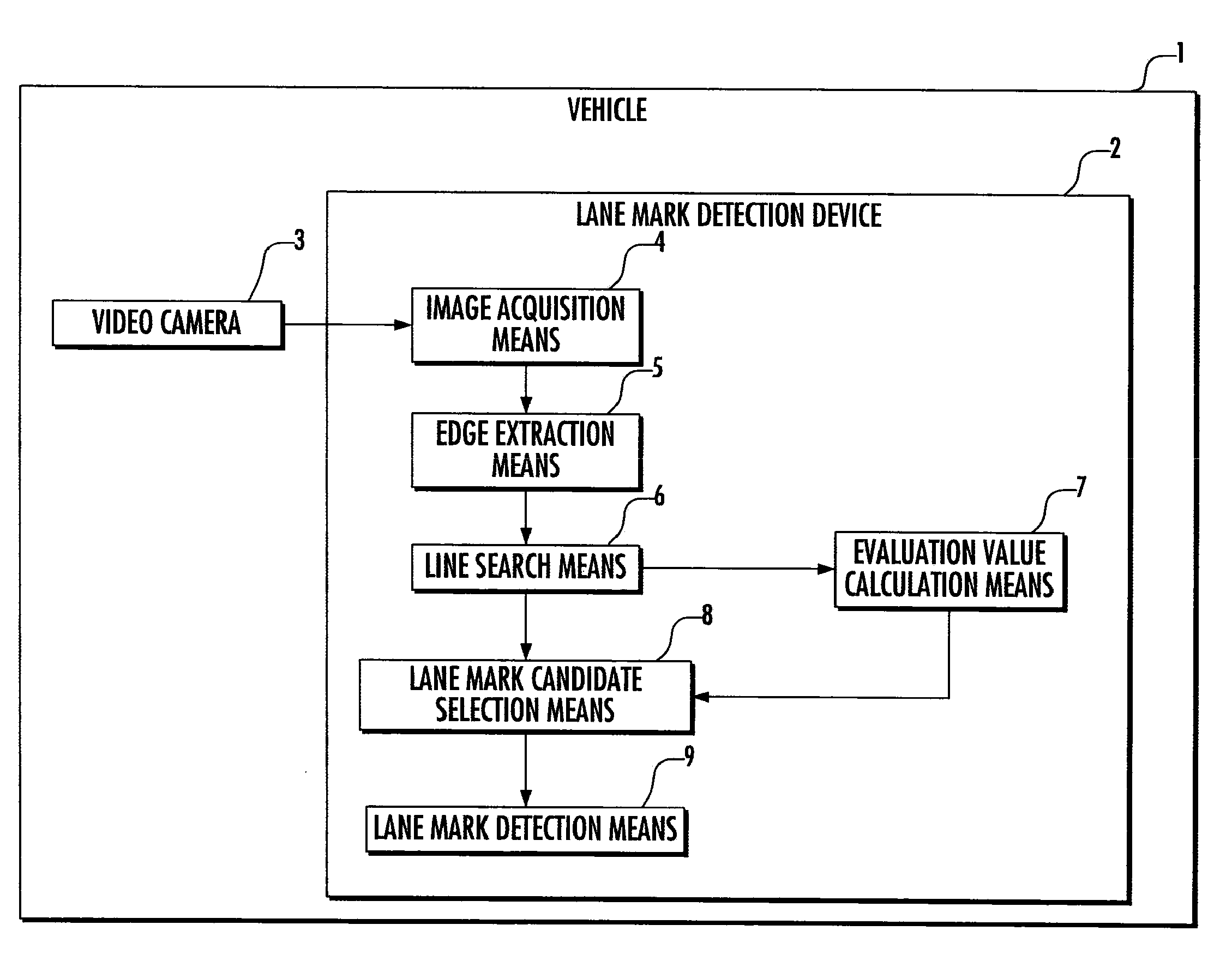
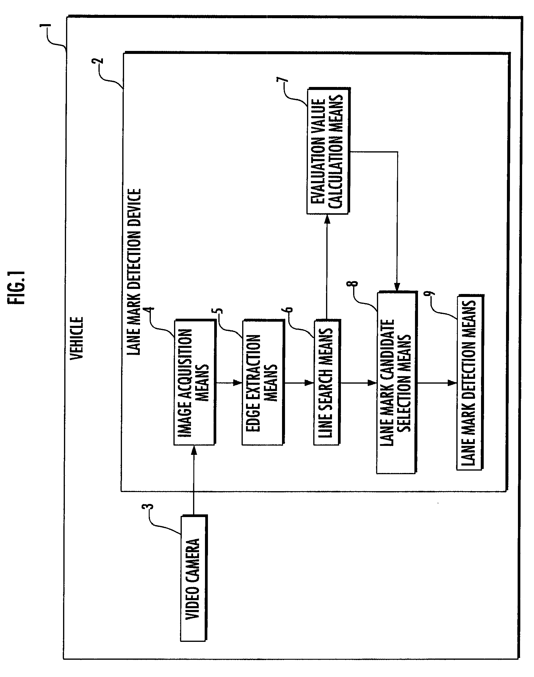
[0030]Referring to FIG. 1, a lane mark detection device 2 is an electronic unit containing a microcomputer and the like and is mounted on a vehicle 1, including an image acquisition means 4 which acquires a road image via a video camera 3 mounted on the vehicle 1, an edge extraction means 5 which extracts edge points from the acquired image, a line search means 6 which searches the extracted edge points for a line component, an evaluation value calculation means 7 which calculates an evaluation value indicating the degree that each line component searched for approximates the linear lane mark on the road, a lane mark candidate selection means 8 which selects lane mark candidates from the line components according to the calculated evaluation values, and a lane mark detection means 9 which detects a lane mark from the selected lane mark candidates.

[0031]The image acquis...

second embodiment

[0062]Subsequently, a second embodiment of the present invention will now be described with reference to FIG. 6 and FIG. 7. This embodiment is equivalent to the first embodiment except that the vehicle 1 is equipped with a vehicle speed sensor 10 and a yaw rate sensor 11 and that the lane mark detection device 2 includes a moving trajectory estimation means 12, a coordinate transformation means 13, a line classification means 14, and an evaluation value filtering means 15. In the following description, like elements to those of the first embodiment are denoted by like reference numerals and the description thereof is omitted.

[0063]In this embodiment, the vehicle 1 is equipped with the vehicle speed sensor 10 which detects a traveling speed (vehicle speed) of the vehicle 1 and the yaw rate sensor 11 which detects a yaw rate of the vehicle 1.

[0064]In addition, the moving trajectory estimation means 12 estimates the moving trajectory of the vehicle 1 on the basis of the vehicle speed o...


PUM


Abstract

A vehicle includes: an image acquisition means (4) which acquires a road image via an imaging means (3); an edge extraction means (5) which extracts edge points from the acquired image; a line search means (6) which searches the extracted edge points for line components; an evaluation value calculation means (7) which calculates an evaluation value indicating the degree that each line component approximates a linear lane mark on the road for the line components searched for; a lane mark candidate selection means (8) which selects line components each having an evaluation value greater than a predetermined threshold value as candidates for a line component corresponding to the lane mark from the line components searched for; and a lane mark detection means (9) which detects the lane mark by determining the line component corresponding to the lane mark from the selected candidates for the line component. This allows the detection accuracy to be increased by preventing an object other than a lane mark on the road from being incorrectly detected as a linear lane mark such as a white line when detecting a linear lane mark such as a white line from the road image.

Description

TECHNICAL FIELD[0001]The present invention relates to a vehicle and a lane mark detection device for detecting a lane mark such as a white line on a road by processing a road image acquired via an imaging means such as a camera.BACKGROUND ART[0002]In recent years, there has been known a technique for detecting a lane mark such as a white line on a road by capturing an image of a road along which a vehicle travels and processing the acquired image with an imaging means such as a CCD camera mounted on the vehicle and for controlling the vehicle or providing a driver with information on the basis of information on a lane (traffic lane) along which the vehicle travels recognized from a detection result (refer to, for example, Japanese Patent Application Laid-Open No. Hei 11-147473 / 1999 (hereinafter, referred to as Patent Document 1).[0003]The steering force assisting device in Patent Document 1 extracts a point where luminance changes from dark to light (positive edge point) and a point...

Claims


Application Information

Patent Timeline
Patent Type & Authority Patents(United States)
IPC IPC(8): H04N7/18
CPCG06K9/00798G06T7/0083G08G1/16G08G1/167B60W30/12B60W2420/42G06T2207/10016G06T2207/20061G06T2207/30256G06T7/12G06V20/588
Inventor UNOURA, KIYOZUMI
Owner HONDA MOTOR CO LTD
Why Eureka
Try Eureka