
Method, device and system for imaging

a technology of imaging and optical arrangement, applied in the field of imaging methods, devices and systems, can solve the problems of cumbersome and costly use of inability to determine the distance between the camera and the objects within the window, and the burden of producing common line of sight optical arrangement, etc., to maximize the dynamic range of imaging system, simplify the processing of detected radiation to determine the distance between the camera and the objects within the window, and improve the effect of accuracy

Inactive Publication Date: 2012-06-26
MICROSOFT INT HLDG BV
View PDF20 Cites 3 Cited by
  • Summary
  • Abstract
  • Description
  • Claims
  • Application Information

AI Technical Summary

Benefits of technology

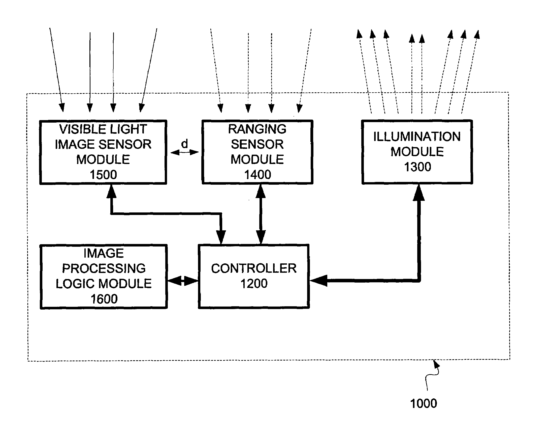
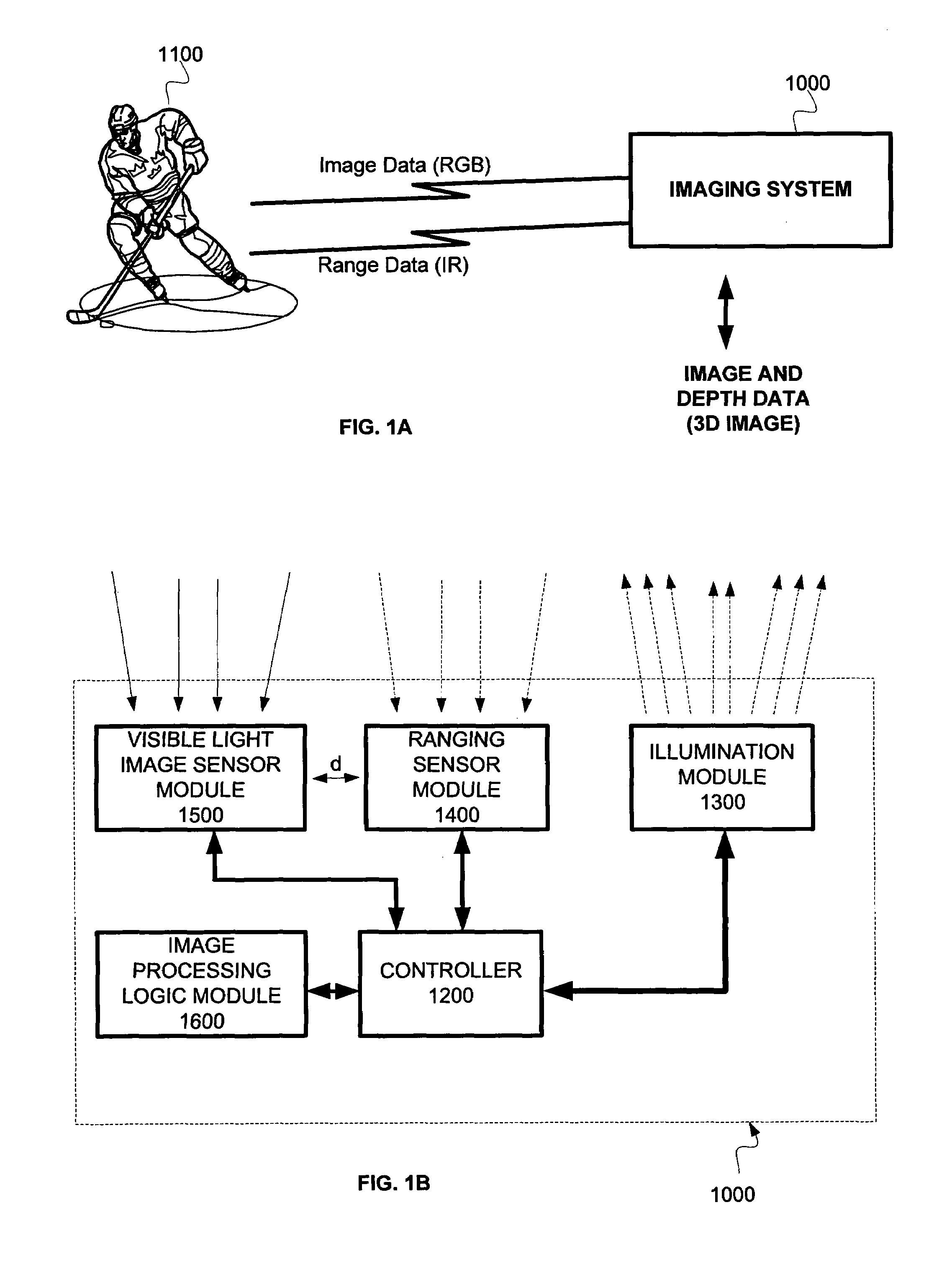
[0022]According to some embodiments of the present invention, image processing logic may include a look-up table for the relative shift of a sensed pixel. The input parameters of the look up table may be parameters of the ranging sensor array (i.e. distance, pixel coordinates). According to yet further embodiments of the present invention, such a look up table may be generated in advance so as to provide a real time calculation of the relative offset, hence enabling the image processing logic to correlate a pixel of the ranging sensor array and a pixel of the visible light sensor array (“corresponding pixels”) in substantially real time (“zero time”).
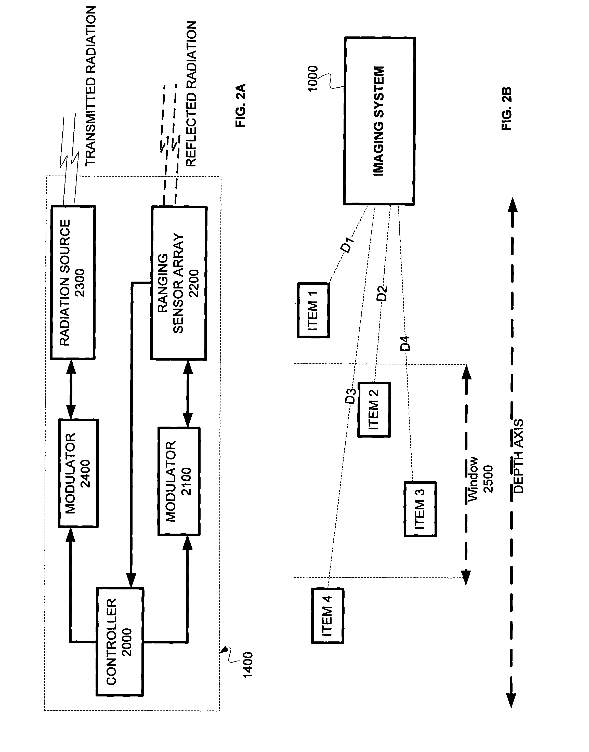
[0025]According to some embodiments of the present invention, the radiation source may be modulated by a first waveform and the reflected radiation in modulated by a second waveform. The shapes of the first and second waveforms and a time delay between the waveforms are adjusted to give a desired functional dependence of the intensity detected at each pixel of the detector array on the distance from the imaging system to the object imaged by the pixel. The first and second waveforms and the delay there between may be adjusted so as to define a distance “window,” i.e., a range of distances of objects from the imaging system over which the distances of the objects may be determined. While the radiation source and the reflected radiation are respectively modulated by the first and second waveforms, the imaging system analyzes images only of objects inside the window. By suitably adjusting the window, the processing of the detected radiation to determine the distances from the camera to the objects within the window is simplified and / or its accuracy is improved. According to yet further embodiments of the present invention, the window is also adjusted to maximize the dynamic range of the imaging system for objects at a range of distances from the camera corresponding to a portion of the scene that is of interest.
[0026]According to some embodiments of the present invention, the first and second waveforms may be such that the source and / or reflected radiation are blocked and unblocked many times during a single field or frame of the detector array. Preferably, the first and second waveforms comprise a plurality of pulses, wherein each pulse of the second waveform follows a corresponding pulse of the first waveform by a predetermined, typically constant, delay. Considering that the duration of a standard NTSC video field is about 16.7 msec, while the durations of the pulses of the first and second waveforms are typically less than one microsecond, it will be appreciated that hundreds or thousands of such pulses may be included in the time of a single field or frame. Such multiple-pulse modulation functions are useful in increasing the signal / noise ratio (“SNR”) of the image produced by the imaging system.
[0027]According to some embodiments of the present invention, the window may be adjusted adaptively so as to acquire images of one or more objects of interest. Preferably, a first window, encompassing a large range of distances from the imaging system, is initially defined by modulating the source and the reflected radiation using waveforms of relatively long duration. An image of the objects of interest is acquired within this window, and the distance to at least one of the objects is determined. A second window is then defined, including the at least one object and preferably encompassing a narrower range of distances than the first window. In this way, a second image is acquired including reduced clutter of objects that are not of interest, and allowing more accurate determination of the distance to the at least one object of interest.

Problems solved by technology

The camera cannot determine the distances to various objects or different points within the range.
The use of common line of sight optical arrangements is, however, both cumbersome and costly.
Complexities associated with producing common line of sight optical arrangements are a burden in the production of multi-dimensional imaging devices and systems.

Method used


Image

  • Method, device and system for imaging
  • Method, device and system for imaging
  • Method, device and system for imaging

Examples


Embodiment Construction

[0043]In the following detailed description, numerous specific details are set forth in order to provide a thorough understanding of the invention. However, it will be understood by those skilled in the art that the present invention may be practiced without these specific details. In other instances, well-known methods, procedures, components and circuits have not been described in detail so as not to obscure the present invention.

[0044]Unless specifically stated otherwise, as apparent from the following discussions, it is appreciated that throughout the specification discussions utilizing terms such as “processing”, “computing”, “calculating”, “determining”, or the like, refer to the action and / or processes of a computer or computing system, or similar electronic computing device, that manipulate and / or transform data represented as physical, such as electronic, quantities within the computing system's registers and / or memories into other data similarly represented as physical qua...


PUM


Abstract

There is provided a novel method, device and system for imaging. According to some embodiments of the present invention, a visible light image sensor array (e.g. Charge-Couple Device (“CCD”) or Complementary Metal-Oxide-Semiconductor (“CMOS”)) and a ranging sensor array may be arranged substantially facing the same direction and having a substantially overlapping field of view. According to further embodiments of the present invention, a range value derived from one or more ranging sensor elements within the ranging sensor array may be correlated with one or more imaging elements within the visible sensor array. Image processing logic may correlate the derived ranging value with the one or more imaging elements as a function of the derived range.

Description

RELATED APPLICATIONS[0001]The present application is a US National Phase of PCT Application No. PCT / IL2007 / 001498, filed on Dec. 4, 2007, which claims the benefit under 35 U.S.C. 119(e) of U.S. Provisional Application 60 / 884,882 filed on Jan. 14, 2007, the disclosures of which are incorporated herein by reference.FIELD OF THE INVENTION[0002]The present invention relates generally to methods, devices and systems for imaging. More specifically, the present invention relates to methods, devices and systems for capturing one or more images of a scene using a visible light image sensor array and a ranging sensor array adapted to output a multi-dimensional (e.g. three dimensional) data set representing the scene.BACKGROUND[0003]Various techniques are known for acquiring three-dimensional images of a scene, i.e., images that include depth or distance information of the scene. Exemplary methods of multi-dimensional imaging include: (1) time-of-flight (i.e. light) measurement, (2) reflected ...

Claims


Application Information

Patent Timeline
Patent Type & Authority Patents(United States)
IPC IPC(8): G01C3/08
CPCG01S7/486G01S17/023G01S17/107G01S17/89A63F2300/1093G01S17/18G01S17/86
Inventor YAHAV, GIORAMANDELBOUM, DAVIDZIGELMAN, GIL
Owner MICROSOFT INT HLDG BV
Learn More