
Real-time high-dynamic imaging method and imaging system

The technology of an imaging system and imaging method, which is applied to the components of the TV system, image communication, TV, etc., can solve the problems of real-time requirements for small delay applications, high calculation result errors, and dynamic image blurring, etc., to achieve small delay, High real-time performance, highlighting the effect of detailed information

Active Publication Date: 2020-08-25
XI'AN INST OF OPTICS & FINE MECHANICS - CHINESE ACAD OF SCI
View PDF8 Cites 3 Cited by
  • Summary
  • Abstract
  • Description
  • Claims
  • Application Information

AI Technical Summary

Problems solved by technology

[0005] The purpose of the present invention is to solve the problems that the existing dynamic range extension method cannot satisfy the application occasions with high real-time requirements and small delay, and there are large errors in calculation results and blurred high-dynamic images. A dynamic imaging method and an imaging system. The method and system combine the image data of the high and low gain output channels on the basis of the existing image detector with high and low gain dual channel simultaneous output, and combine the high and low gain output channels to convert the high and low gain Low-gain images are weighted and fused according to the calculated weight ratio to obtain high dynamic range images

Method used


Image

  • Real-time high-dynamic imaging method and imaging system
  • Real-time high-dynamic imaging method and imaging system
  • Real-time high-dynamic imaging method and imaging system

Examples


Embodiment Construction

[0046] The content of the present invention will be further described in detail below in conjunction with the accompanying drawings and specific embodiments.

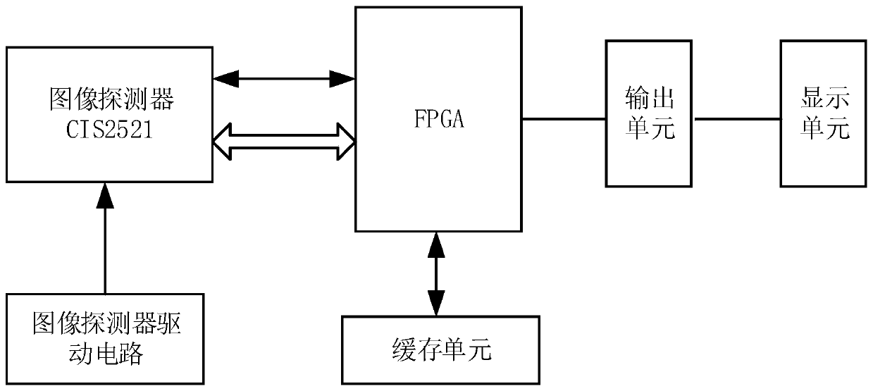
[0047] Such as figure 1 As shown, the present invention provides a real-time high dynamic imaging system, including an image detector, an image detector driving circuit, FPGA, a cache unit, an output unit and a display storage unit. Among them, the image detector is an image detector with high-gain and low-gain dual-channel simultaneous output, which is used to realize photoelectric conversion, and convert the reflected light signal of the shooting scene into a digital video signal for output. The image detector driving circuit is connected with the image detector and is used for providing the working voltage to the image detector. The FPGA is connected with the image detector, and is used to generate the working sequence of the image detector, collect and process the image data output by the image detector, and so on....


PUM


Abstract

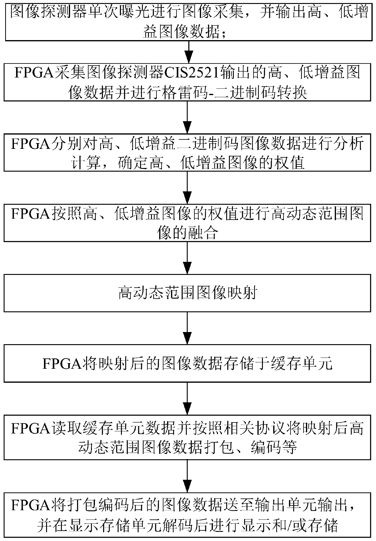
The invention provides a real-time high-dynamic imaging method and imaging system, and solves the problems that an existing dynamic range extension method cannot meet the application occasions with high real-time requirements and small time delay, calculation results have large errors, and high-dynamic images are blurred. The method comprises the following steps: 1, enabling an image detector to output high-gain and low-gain image data; 2, performing Gray code-binary code conversion on the high-gain image data and the low-gain image data; 3, obtaining weights of the high-gain image and the low-gain image; 4, fusing the high dynamic range images; 5, performing high dynamic range image mapping; 6, storing the mapped high dynamic range image data in a cache unit; 7, reading cache unit data, and packaging and encoding the mapped high dynamic range image data; and 8, sending the packaged and encoded image data to an output unit for outputting.

Description

technical field [0001] The invention belongs to the field of real-time image processing, and in particular relates to a real-time high dynamic imaging method and imaging system, in particular to a high dynamic image imaging system and imaging method based on single-exposure high-gain and low-gain image fusion. Background technique [0002] The dynamic range of a real scene refers to the illuminance ratio of the brightest part to the darkest part in the scene, which is usually expressed in logarithms, and the unit is dB. The illuminance range in nature covers a very wide range, the maximum dynamic range is as high as 160dB, and the dynamic range that the human eye can perceive can reach 100dB. [0003] The dynamic range of the image is an important parameter to characterize the imaging quality of the imaging system. At present, most digital imaging systems are still 8-bit quantized display, and the output image can only record a limited range of grayscale and color levels, an...

Claims


Application Information

Patent Timeline
Patent Type & Authority Applications(China)
IPC IPC(8): H04N5/235H04N5/265
CPCH04N5/265H04N23/741
Inventor 王华陈耀弘刘庆王华伟
Owner XI'AN INST OF OPTICS & FINE MECHANICS - CHINESE ACAD OF SCI
Learn More