Sensing force during partial and total knee replacement surgery

a knee replacement and sensor technology, applied in the field of medical surgical devices, systems and methods, can solve the problems of limited range of motion, poor patellar tracking, and significant pain of patients, and achieve the effects of standardized and repeatable, accurate and quantifiable measurement of force, and improved ligament tension balancing

Active Publication Date: 2012-07-03
SYNVASIVE TECH
View PDF25 Cites 116 Cited by
  • Summary
  • Abstract
  • Description
  • Claims
  • Application Information

AI Technical Summary

Benefits of technology

[0013]Embodiments of the invention provide systems, devices, and methods for measuring forces in the space of a knee during surgery. Such forces can be caused by tension in the ligaments of the knee. A femoral member is engaged with a distal femur. While the knee is flexed, partially extended, or fully extended, a force sensor and a gauge shim can be placed in the gap between the end of the femoral member and the tibial plateau to measure the forces therebetween. The force sensor provides an accurate and quantifiable measurement of force, making knee replacement surgery and ligament tension balancing more accurate, standardized and repeatable. The force sensor comprises an elongate housing which comprises a thin force sensing distal portion and a proximal handle portion. A sensor element is disposed within the thin force sensing distal portion of the elongate housing.

Problems solved by technology

This bone-on-bone contact can cause significant pain, discomfort, and disability for a patient and will often necessitate knee replacement or knee arthroplasty.
A challenge in knee replacement surgeries, including both TKA and UKA, is the proper balancing of ligament tension, especially of the medial and lateral collateral ligaments, through the full range of motion of the knee, from a flexed position to a fully extended position.
Uneven ligament tension after knee replacement surgery will typically lead to symptoms including joint instability and poor patellar tracking, limited range of motion, impaired function of the knee, and uneven, increased wear and / or loosening of the prosthetic device.
Balancing ligament tension during knee replacement surgery is complicated by the fact that the natural knee does not operate like a hinge moving about a single axis.
Thus, the ligaments of the knee, along with the femur, tibia and patella, create a dynamic bio-mechanism, making ligament tension balancing in TKA surgery challenging.
One technique for balancing collateral ligament tension during a knee replacement procedure involves cutting fibers of one or both ligaments to decrease ligament tension—a technique referred to as “ligament release.” A disadvantage of this technique is that the cutting of ligament tissue weakens the ligament(s) and leaves less room for error if future ligament releases or knee replacement procedures are required.
However, it is often very challenging to position the femoral bone cuts and femoral prosthetic component to provide ideal ligament tension through the full range of motion of the knee.
This is due primarily to the complexity of motion about the knee, as described above, and the difficulty of placing the femoral component so as to maintain desired ligament tension through the full range of motion.

Method used


Image

  • Sensing force during partial and total knee replacement surgery
  • Sensing force during partial and total knee replacement surgery
  • Sensing force during partial and total knee replacement surgery

Examples


Embodiment Construction

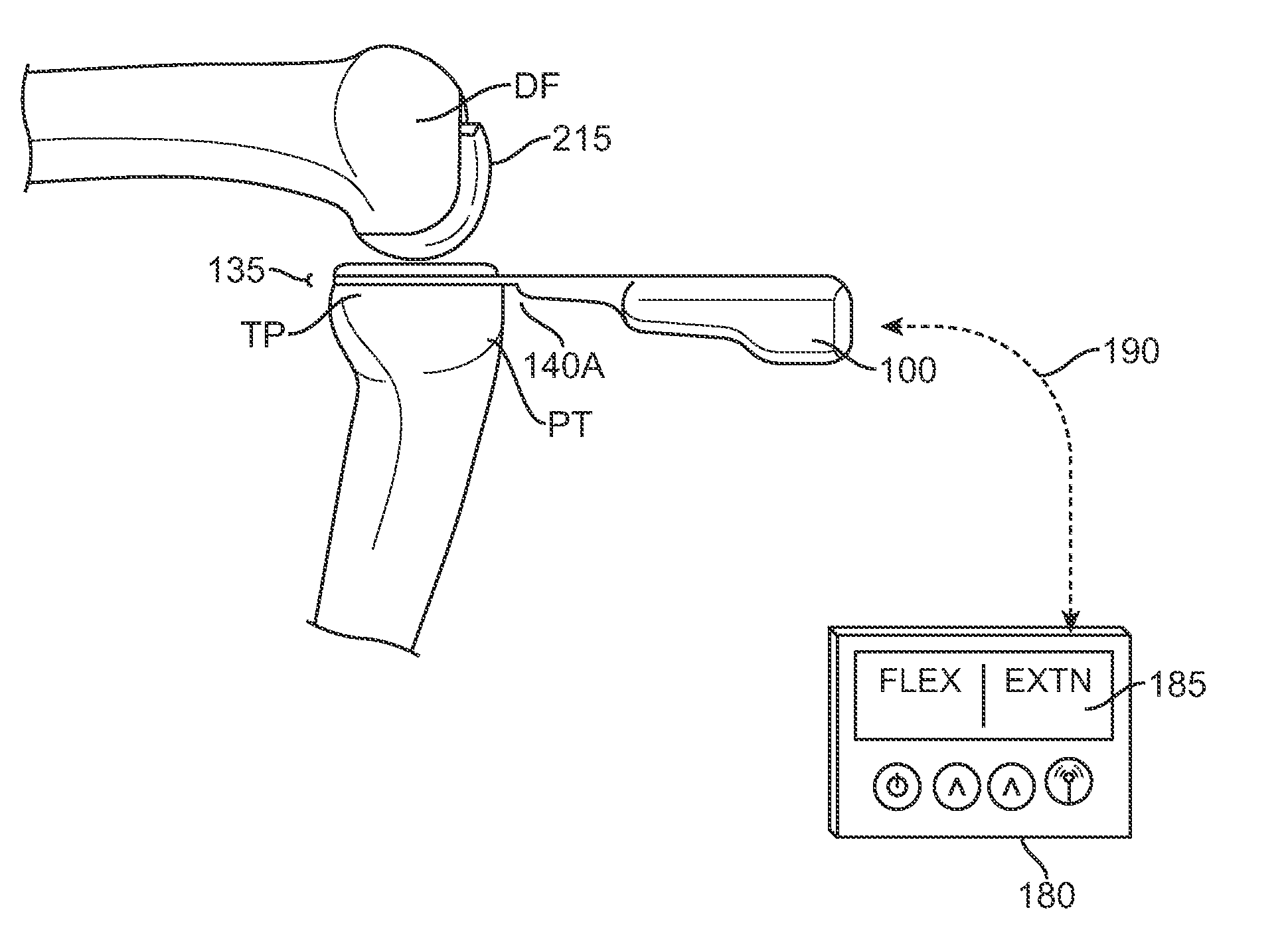
[0048]The following exemplary embodiments of systems, devices and methods will be described in the context of sensing force during partial and total knee replacement surgery. This is intended to be for illustrative purposes only and one of ordinary skill in the art will recognize that the systems, devices and methods disclosed herein may be used in a number of other applications and therefore are not limited to knee surgery. The features and advantages will become apparent upon reading the following detailed description and referring to the accompanying drawings in which like numbers refer to like parts throughout.

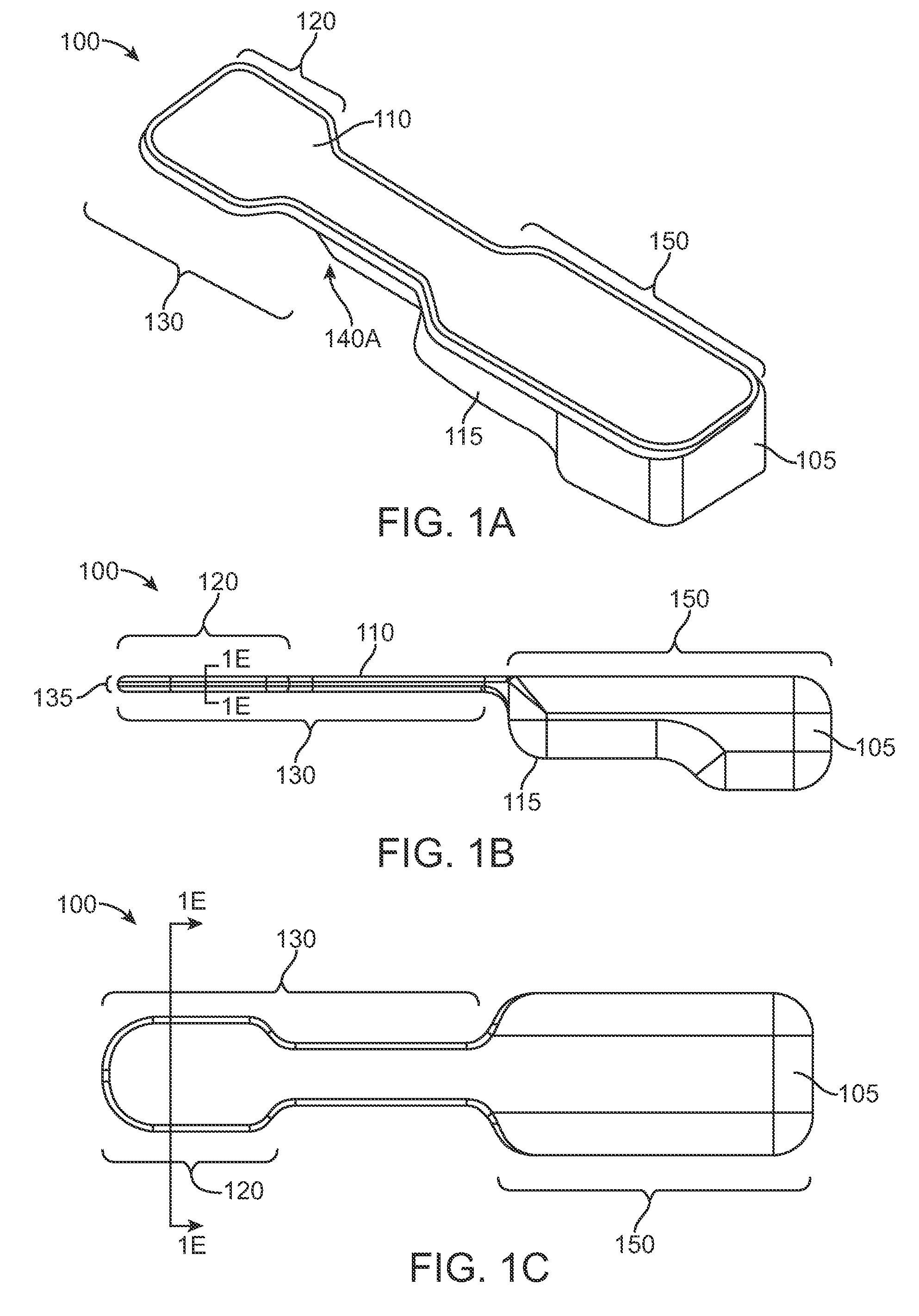
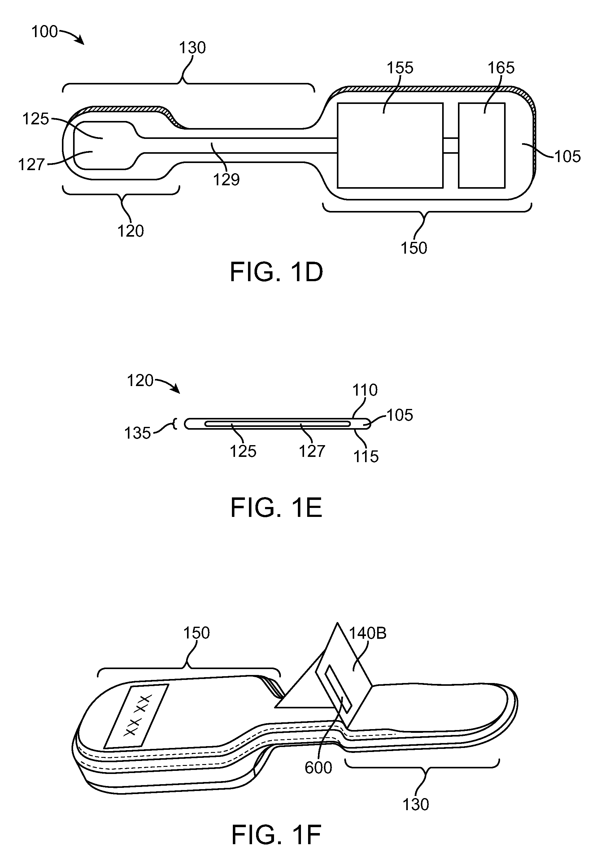
[0049]FIGS. 1A-1F show a handheld force sensor 100 according to embodiments of the invention. FIG. 1A shows a perspective view of force sensor 100. FIG. 1B shows a side view of force sensor 100. FIG. 1C shows a top view of force sensor 100. FIG. 1D shows a cross section of force sensor 100 as viewed from the top down. FIG. 1E shows a cross section of a distal portion of fo...


PUM


Abstract

Systems, devices, and methods are provided for measuring forces in the space of a knee during surgery. Such forces can be caused by tension in the ligaments of the knee. A femoral member is engaged with a distal femur. While the knee is flexed, partially extended, or fully extended, a force sensor and a gauge shim can be placed in the gap between the femoral member and the tibial plateau to measure the forces therebetween. The force sensor provides an accurate and quantifiable measurement of force, making knee replacement surgery and ligament tension balancing more accurate, standardized and repeatable. The force sensor comprises an elongate housing which comprises a thin force sensing distal portion and a proximal handle portion.

Description

CROSS-REFERENCE TO RELATED APPLICATIONS[0001]The present application is a non-provisional of, and claims the benefit of priority under 35 U.S.C. §119(e), U.S. Provisional Application No. 61 / 090,535 filed Aug. 20, 2008, the entire contents of which are incorporated herein by reference.BACKGROUND OF THE INVENTION[0002]The present invention relates generally to medical surgical devices, systems, and methods. More specifically, the invention relates to devices, systems and methods for enhancing knee surgery including measuring forces in flexion and / or extension gap(s) during knee arthroplasty.[0003]The knee is generally defined as the point of articulation of the femur with the tibia. Structures that make up the knee include the distal femur, the proximal tibia, the patella, and the soft tissues within and surrounding the knee joint, the soft tissues including the ligaments of the knee. The knee is generally divided into three compartments: medial (the inside part of the knee), lateral ...

Claims


Application Information

Patent Timeline
Patent Type & Authority Patents(United States)
IPC IPC(8): A61B5/103A61B5/117
CPCA61F2/4657A61B17/88A61F2/32A61F2/38A61F2/3804A61F2/40A61F2/4202A61F2/44A61F2/4684A61F2002/4666A61F2002/4687
Inventor FISHER, MICHAEL G.SIZELOVE, ANDREWBEREND, KEITH R.MURRAY, DAVID W.
Owner SYNVASIVE TECH
Why Eureka
Try Eureka