
Machining head, nozzle changer and laser beam machining apparatus

a technology of laser beam machining and nozzle changer, which is applied in the direction of positioning apparatus, manufacturing tools, metal-working machine components, etc., can solve the problems of poor nozzle positioning reproducibility, nozzle replacement, and poor alignment of the axes of the machining head, so as to achieve high-quality machining and easy replacement of the nozzle

Inactive Publication Date: 2012-07-03
MITSUBISHI ELECTRIC CORP
View PDF22 Cites 10 Cited by
  • Summary
  • Abstract
  • Description
  • Claims
  • Application Information

AI Technical Summary

Benefits of technology

The present invention provides a laser machining head, nozzle changer, and laser beam machining apparatus that make it easy to replace the nozzle without the need to perform a nozzle alignment task at each cycle of nozzle replacement. This improves the efficiency of machining. The laser machining head includes a machining head element with an inner-head channel for laser light and assist gas, a separate nozzle with an inner-nozzle channel connected to the inner-head channel, and a nozzle orifice through which the laser light and assist gas are directed toward the work. The nozzle is locked in position using pins and a pin-locking part on the machining head element. The nozzle changer includes a nozzle supporting rod and a nozzle changing unit that rotates the nozzle to align with the machining head element and disengage from it. The laser beam machining apparatus includes a laser oscillation unit, an assist gas supply unit, a stage, and a moving device for adjusting the position of the stage relative to the machining head element. These improvements make it easier to replace the nozzle and improve the efficiency of machining.

Problems solved by technology

Consequently, there arises a problem that the nozzle can be replaced only with poor alignment of the axes of the machining head and the nozzle, or with poor concentricity thereof, and poor nozzle positioning reproducibility.
A further problem which develops when the axes of the machining head and the nozzle are poorly aligned or when the nozzle is not positioned at an ideal distance form the work is that each cycle of nozzle replacement requires a nozzle alignment task to be done and a large amount of time for performing the task to accomplish high-quality machining.

Method used


Image

  • Machining head, nozzle changer and laser beam machining apparatus
  • Machining head, nozzle changer and laser beam machining apparatus
  • Machining head, nozzle changer and laser beam machining apparatus

Examples


first embodiment

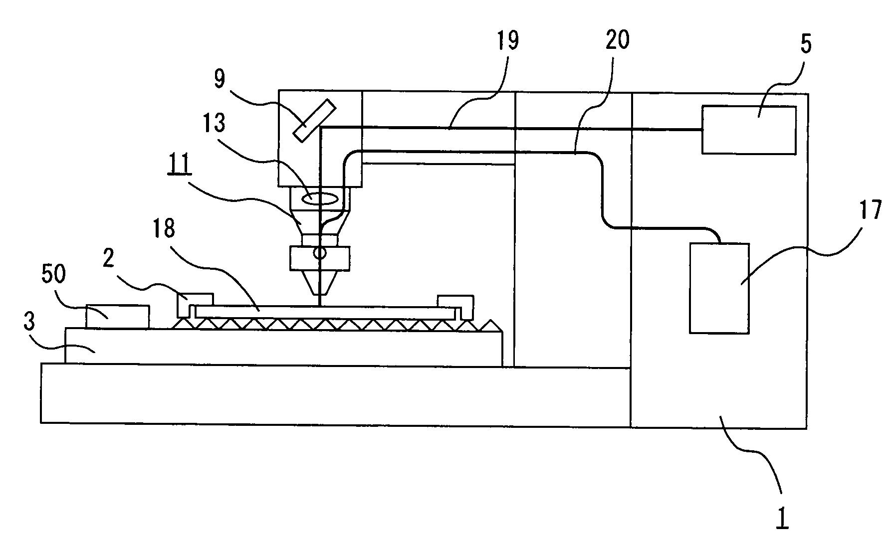
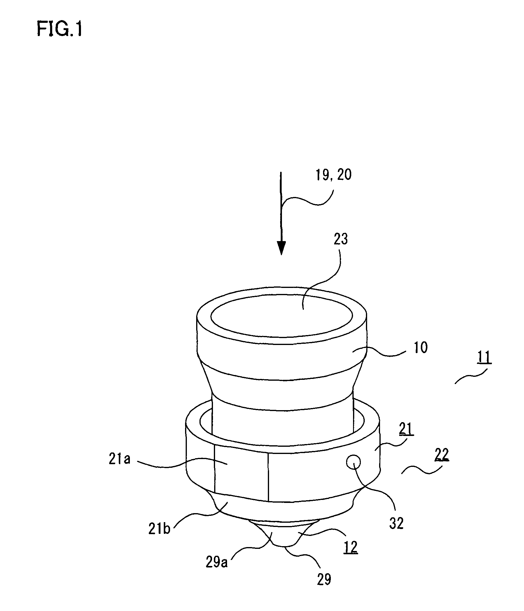
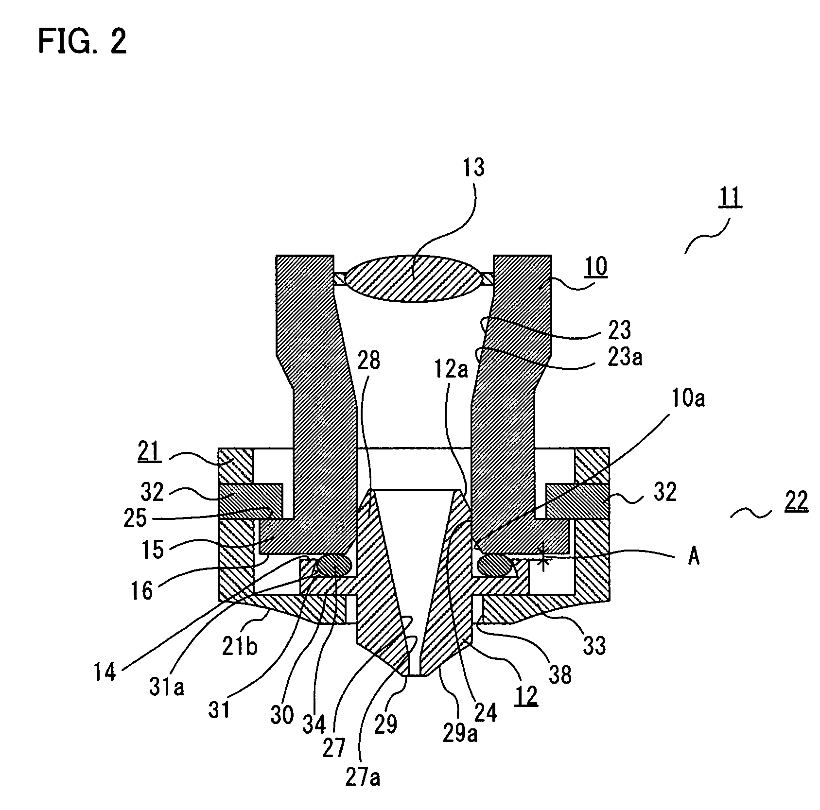
[0040]FIG. 1 is a perspective view showing the structure of a machining head 11 according to a first embodiment of the invention, FIG. 2 is a cross-sectional view of the machining head 11 of FIG. 1, FIG. 3 is a perspective view of a machining head element 10 of the machining head 11 of FIG. 1, FIG. 4 is a perspective view of a nozzle element 12 of a nozzle 22 of the machining head 11 of FIG. 1, FIGS. 5A and 5B are perspective and top views of a nozzle fixture 21 of the nozzle 22 of the machining head 11 of FIG. 1, FIG. 6 is a diagram schematically showing the structure of a laser beam machining apparatus 1 employing the machining head 11 shown in FIG. 1, FIGS. 7A, 7B, 8A and 8B are diagrams for explaining potential problems which may occur in the machining head 11 of the laser beam machining apparatus 1, FIG. 9 is a cross-sectional diagram for explaining vertical dimensional accuracy of the machining head 11 shown in FIG. 1, FIGS. 10A, 10B, 10C, 11A and 11B are cross-sectional diagr...


PUM

PropertyMeasurementUnit
wavelengthaaaaaaaaaa
distanceaaaaaaaaaa

Abstract

A machining head includesa machining head element having an inner-head channel for passing laser light and assist gas,the nozzle having an inner-nozzle channel connecting to the inner-head channel and a nozzle orifice,pins protruding radially inward from a curved inner surface of the nozzle,a pin-locking part formed on the outside of the machining head element, the pin-locking part having pin-fitting openings,a head alignment part formed on a nozzle-side end surface of the machining head element,a nozzle alignment part formed on the nozzle at a location where the nozzle is aligned with the machining head element, andan O-ring fitted between the head alignment part and the nozzle to create a clearance between the head alignment part and the nozzle alignment part for mutual alignment.

Description

BACKGROUND OF THE INVENTION[0001]1. Field of the Invention[0002]The present invention relates generally to a laser beam machining apparatus and, more particularly, to a laser machining head of a laser beam machining apparatus provided with an easily replaceable nozzle as well as to a nozzle changer.[0003]2. Description of the Background Art[0004]There exist various types of conventionally known laser beam machining apparatuses used for machining (e.g., hot-cutting) a workpiece by use of laser light. In a floor-mount laser beam machining apparatus, for example, a nozzle through which assist gas is ejected against a work is provided on an optical axis of laser light at a lower part of a machining head. Being an element normally positioned close to a machining point, the nozzle is apt to collect debris (slag and dross) molten from the work, or even melt due to reflected laser light or the heat of adhering molten material of the work, during laser cutting operation. Different types of n...

Claims


Application Information

Patent Timeline
Patent Type & Authority Patents(United States)
IPC IPC(8): B23K26/14B23K26/16
CPCB23K26/1482Y10T483/17
Inventor AKIYAMA, TAKASHIHASEGAWA, MASAHIKOKATASE, KAZUNOBUYOKOI, SHIGERU
Owner MITSUBISHI ELECTRIC CORP
Learn More