Resonant, contactless radio frequency power coupling

a technology of contactless and radio frequency, applied in the field of contactless power transmission, can solve problems such as complicated rf power transfer in ocean environment, and achieve the effect of avoiding some of the costs and disadvantages

Inactive Publication Date: 2012-07-03
LOCKHEED MARTIN CORP
View PDF4 Cites 133 Cited by
  • Summary
  • Abstract
  • Description
  • Claims
  • Application Information

AI Technical Summary

Benefits of technology

[0015]The invention provides a way to transfer externally generated electrical power to an storage system that avoids some of the costs and disadvantages of the prior art.
[0017]The illustrative embodiment of the present invention is a resonant RF power coupling suitable for high power transfer applications. In the illustrative embodiment, the power coupling includes a transmit coupling and a receive coupling, each of which include a resonant element. A high-power RF generator is coupled to the transmit coupling and an storage system is coupled to the output coupling. In some embodiments, efficient transmission of power to an storage system within a vehicle submerged in seawater is enabled. Embodiments of the present invention overcome some of the inefficiencies typically associated with resonant power transfer in seawater.
[0019]In some embodiments, RF power is transferred between a pair of helical resonators with their open ends abutted. The helical resonators resonate at the operating frequency of the RF power transfer system, as well as at harmonics of this frequency. As a result, multiple frequencies of an RF signal are transmitted from the transmit coupling to the receive coupling, thereby enabling high-efficiency power transfer.
[0020]The inventive power coupling is relatively less sensitive to misalignment than prior art systems. Further, the present invention enables hermetic sealing of both the power source and a submerged instrumentation package. Embodiments of the invention are lighter and more robust than non-resonant, non-direct contact (no metal-to-metal contact) power coupling systems. Further, embodiments of the present invention have much higher power density than prior-art capacitive power coupling systems. A key advantage of embodiments of the present invention is the ability to avoid corrosion (galvanic and otherwise) and / or the complex and problematic seals that are required for use with direct-contact power coupling systems.
[0021]Although particularly well-suited for use in an ocean environment, resonant RF power couplings described herein can be used to advantage in any environment where contactless power transfer is desired. In particular, and among other benefits, embodiments of the invention: (1) enable rapid power transfer; and (2) enable improved isolation of power equipment from power spikes and transients, such as lightning and EMP bursts.

Problems solved by technology

RF power transfer in an ocean environment is complicated by the conductivity of seawater.

Method used


Image

  • Resonant, contactless radio frequency power coupling
  • Resonant, contactless radio frequency power coupling
  • Resonant, contactless radio frequency power coupling

Examples


Embodiment Construction

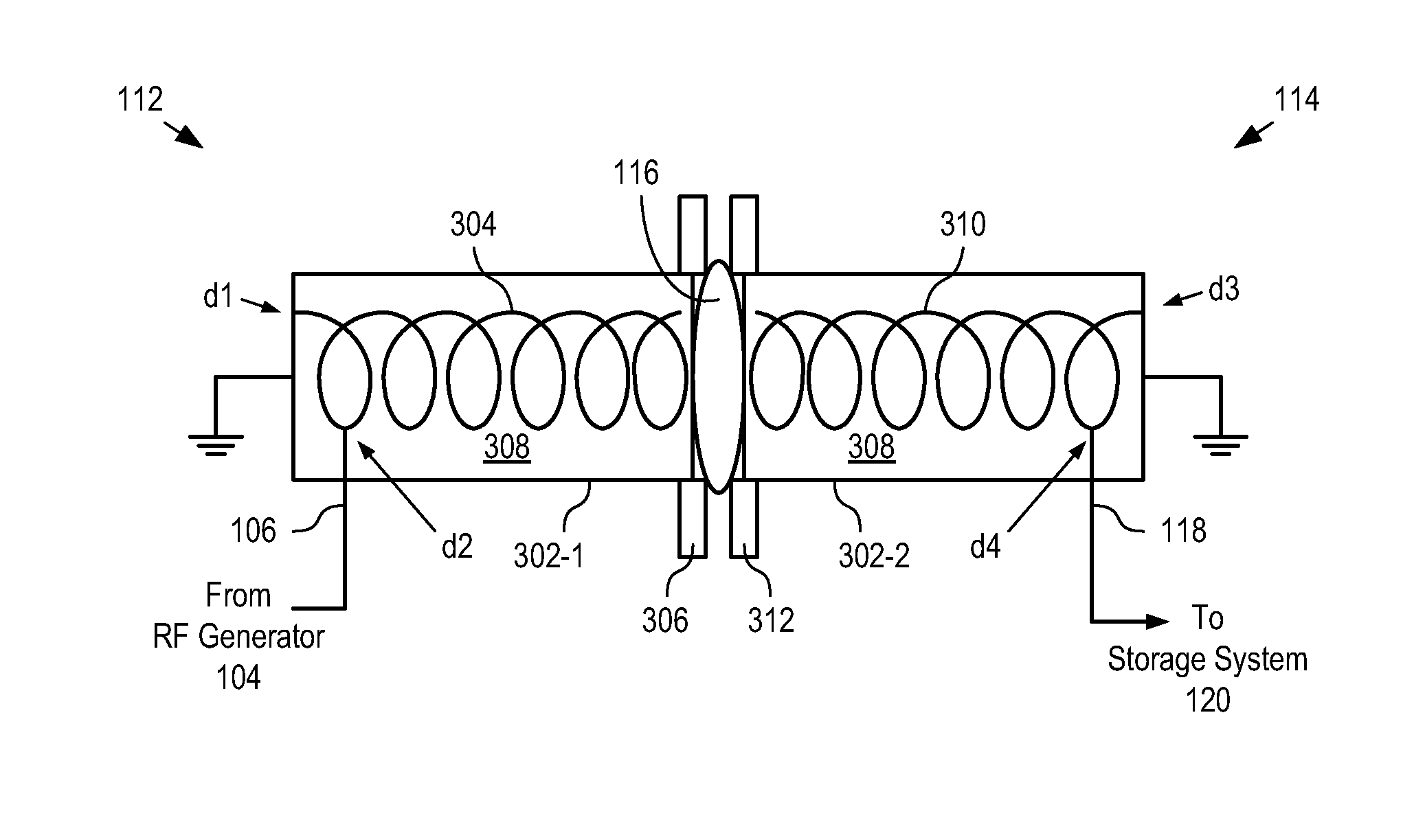
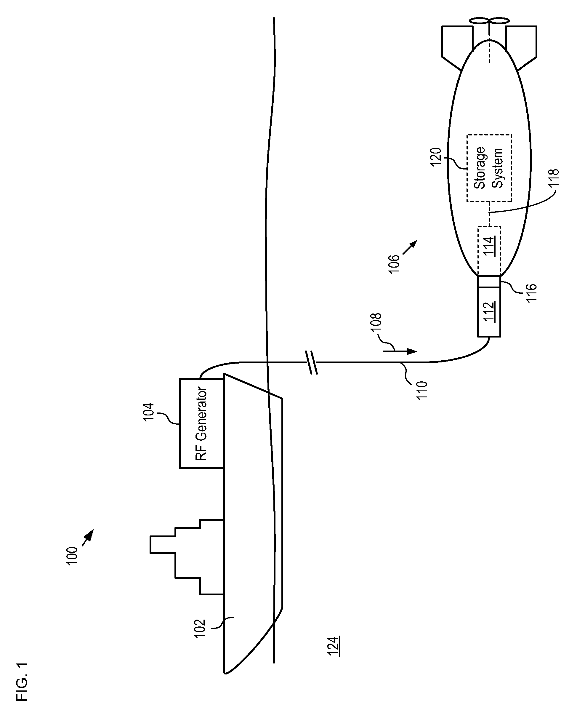
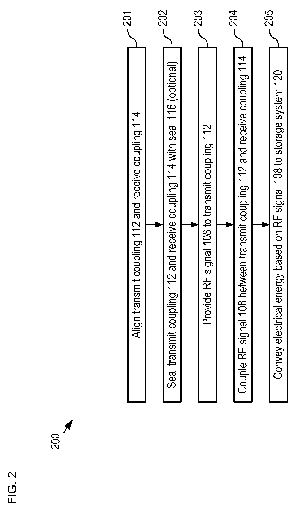
[0031]FIG. 1 depicts a schematic drawing of an RF power coupling system in accordance with an illustrative embodiment of the present invention. System 100 enables rapid charging of an storage system included in an AUV while the AUV is submerged in a seawater environment. System 100 comprises RF generator 104, cable 110, transmit coupling 112, and receive coupling 114. Although the illustrative embodiment comprises an RF power coupling system that is configured for charging a submerged AUV, it will be clear to one skilled in the art, after reading this specification, how to specify, make, and use alternative embodiments of the present invention that are suitable for charging battery-powered land-based vehicles, surface-based nautical vessels, and aircraft.

[0032]RF generator 104 is mounted on ship 102, which is located at the surface of ocean 124. RF generator 104 is an RF generation system capable of generating hundreds of kilowatts (kW) of RF power at a frequency of 30 MHz. RF gener...


PUM

PropertyMeasurementUnit
frequenciesaaaaaaaaaa
frequencyaaaaaaaaaa
diameteraaaaaaaaaa

Abstract

A resonant, contactless, RF power coupling suitable for high power-density applications and for use in an ocean environment is disclosed. In the illustrative embodiment, the power coupling includes a transmit coupling and a receive coupling, each of which include a resonant element. A high-powered RF generator is coupled to the transmit coupling and a rectifier circuit is coupled to the output coupling. Each of the resonant elements is disposed in its own electrically-conductive canister and advantageously potted in an appropriate insulating dielectric. Each canister has an open end to facilitate inductive coupling between the two resonant elements. In order to exclude seawater from the interface between the canisters, a seal of compliant material is disposed therebetween.

Description

CROSS REFERENCE TO RELATED APPLICATIONS[0001]This case claims priority to U.S. Provisional Patent Application Ser. No. 61 / 079,666, filed Jul. 10, 2008, which is incorporated by reference.[0002]In addition, the underlying concepts, but not necessarily the language, of the following cases are incorporated by reference:[0003](1) U.S. patent application Ser. No. 12 / 396,349, filed Mar. 2, 2009; and[0004](2) U.S. patent application Ser. No. 12 / 411,824, filed Mar. 26, 2009.[0005]If there are any contradictions or inconsistencies in language between this application and one or more of the cases that have been incorporated by reference that might affect the interpretation of the claims in this case, the claims in this case should be interpreted to be consistent with the language in this case.FIELD OF THE INVENTION[0006]The present invention relates to power transmission in general, and, more particularly, to contactless power transmission.BACKGROUND OF THE INVENTION[0007]Electrically powered...

Claims


Application Information

Patent Timeline
Patent Type & Authority Patents(United States)
IPC IPC(8): H01F38/14H01F27/28
CPCB60L11/182H02J17/00H02J7/025Y02T90/14B60L2200/32Y02T90/122Y02T10/7005Y02T10/7072H02J50/12B60L53/122Y02T90/16Y02T10/70H02J50/20H02J50/70H02J50/90Y02T90/12
Inventor HOWARD, ROBERT JAMESRAPP, JOHN W.SOONACHAN, STANLEY
Owner LOCKHEED MARTIN CORP
Why Eureka
Try Eureka