Relating to driving brushless DC (BLDC) motors

a brushless dc, motor technology, applied in the direction of motor/generator/converter stopper, electronic commutator, dynamo-electric converter control, etc., can solve the problem of less flexibility, and achieve the effect of reducing the effect of nois

Active Publication Date: 2012-07-03
MELEXIS TECH NV
View PDF23 Cites 20 Cited by
  • Summary
  • Abstract
  • Description
  • Claims
  • Application Information

AI Technical Summary

Benefits of technology

[0011]By generating and using an interpolation of the back EMF, the above method can reliably determine the zero crossing point even if the zero crossing point occurs outside the undriven period. This enables the undriven period to be kept short thus improving torque and reducing noise whilst still enabling a sufficiently accurate motor position to be calculated when the motor speed varies. This method is also less affected by noise and thus more reliable for detecting zero crossing points at low motor speeds.
[0013]The undriven period may be provided by an interruption of the driving waveform. The interruption may occur in response to a suitable interrupt signal. The interruption may end in response to a suitable interrupt end signal. Alternatively, the undriven period may be an integral part of the driving waveform. Such a method eliminates the need for an interrupt signal but may be less flexible.
[0015]Each sample may be an instantaneous sample of the back EMF signal. Preferably, each sample comprises an integration of the back EMF signal over an integration period. By integrating the back EMF signal, effectively an average over the integration period is taken, thus reducing the effects of noise. The sampling may take place in response to suitable integration start and stop signals.

Problems solved by technology

Such a method eliminates the need for an interrupt signal but may be less flexible.

Method used


Image

  • Relating to driving brushless DC (BLDC) motors
  • Relating to driving brushless DC (BLDC) motors
  • Relating to driving brushless DC (BLDC) motors

Examples


Embodiment Construction

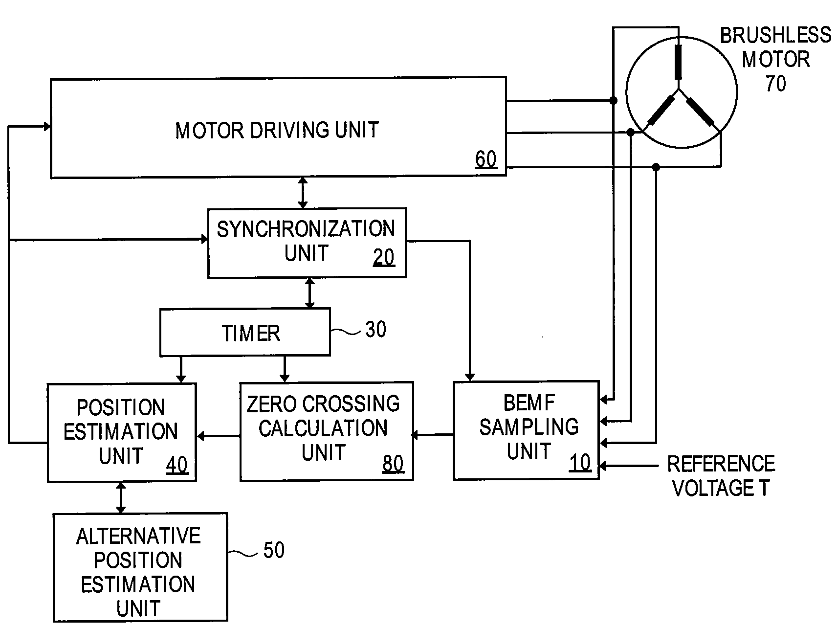
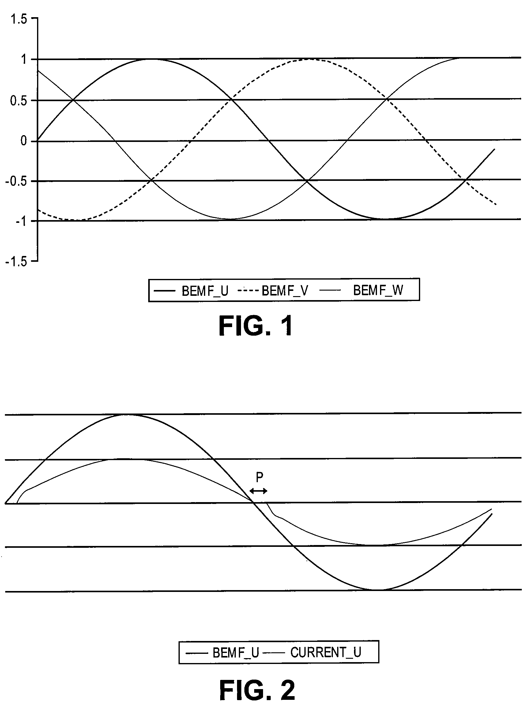
[0045]Referring to FIG. 1, there is shown the induced back EMF signals BEMF_U, BEMF_V, BEMF_W in three phase windings U, V, W of a three phase electric motor. As they are illustrated, the back EMF signals are substantially sinusoidal but they may in other situations be substantially trapezoidal. The three back EMF signals are 120° out of phase with each other. Each instance when a back EMF signal BEMF_U, BEMF_V, BEMF_W is zero indicates that the rotor of the motor is aligned with the respective phase U, V, W and thus allows the instantaneous rotor position to be determined. In order to keep track of the rotor position and thereby ensure the correct driving waveforms are supplied to each phase winding U, V, W the back EMF signals BEMF_U, BEMF_V, BEMF_W are monitored to detect the zero crossing points. In the example shown in FIG. 1, the zero crossings occur in the order BEMF_U (rising signal), BEMF_W (falling signal), BEMF_V (rising signal), BEMF_U (falling signal), BEMF_W (rising si...


PUM


Abstract

In a three phase BLDC motor the rotor position is monitored by detecting the zero crossing points of the induced back EMF signals BEMF_U, BEMF_V, BEMF_W in the phase windings U, V, W. As they are illustrated, the back EMF signals are substantially sinusoidal but they may in other situations be substantially trapezoidal. The three back EMF signals are 120° out of phase with each other. In order to accurately monitor the back EMF in a phase winding, the driving waveform for each phase U, V, W includes an undriven period P close to the expected zero crossing point. The period P can be a preset part of the driving waveform or can be an interruption of the normal driving waveform in response to suitable interrupt signals. In order to determine the zero crossing points of each back EMF signal, two (or more) samples of the back EMF are taken during the undriven period P and used to interpolate the back EMF signal to determine the zero crossing point.

Description

CROSS-REFERENCES TO RELATED APPLICATIONS[0001]This application claims priority to UK 0717851.0, filed Sep. 13, 2007, and which is hereby incorporated by reference in its entirety for all purposes.BACKGROUND[0002]The present invention relates to methods and systems used to drive multiphase brushless DC motors.[0003]The magnetic field used to turn a permanent magnet rotor is generated using three (or more) interconnected phase windings in the stator of the motor. In a bipolar mode the current is driven through only two phase windings at a time and the third undriven phase winding is used to monitor the back EMF voltage. By monitoring the back EMF voltage, the position of the rotor can be determined. This is achieved by detecting the zero crossing point of the monitored back EMF waveform within the phase winding, the zero crossing point occurring when the rotor is in a defined position. If the position of the rotor is known, the driving of the phase windings may be synchronised with th...

Claims


Application Information

Patent Timeline
Patent Type & Authority Patents(United States)
IPC IPC(8): H02P6/18
CPCH02P6/182H02P2209/11H02P2209/07
Inventor PAINTZ, CHRISTIANFREITAG, THOMASKLOSE, DETLEFREINHARDT, ENRICO
Owner MELEXIS TECH NV
Why Eureka
Try Eureka