Bridge and method for manufacturing the bridge

a manufacturing method and bridge technology, applied in bridge applications, bridge types, bridges, etc., can solve the problems of large wind surface, heavy load on the bridge, slow construction and construction of heavy structures, etc., and achieve the effect of reducing construction costs, reducing construction costs, and improving construction efficiency

Inactive Publication Date: 2012-07-10
MIETTINEN ENSIO JOHANNES
View PDF15 Cites 24 Cited by
  • Summary
  • Abstract
  • Description
  • Claims
  • Application Information

AI Technical Summary

Benefits of technology

[0009]The invention can be utilized for transport of liquid, gaseous and solid materials or as a passing bridge for light traffic. The outer appearance of a bridge having a closed continuous surface is neat. By integrating between the tubes of the bridge thin walled utility pipes used for transport of liquid, gas fog or steam or functioning as pneumatic conveyors for particulate solid matter, an ultra light but extremely rigid construction is achieved. The idea is to used utility pipes as constructional elements instead of carrying their weight by a separate support structure. The net weight of the bridge, i.e. the weight of the material to be transported compared to the gross weight, i.e. to the weight of the bridge together with the material to be transported is exceptionally favorable. Stiffness and rigidity also enable use of long spans between supports of the bridge which reduces the required footprint of the bridge on the ground or floor as well as the amount of the construction material needed. The combination of wide spans and ultra light construction exceptionally large savings can be made in the use of construction materials.
[0011]The support legs of the bridge may be constructed according to same principle by using at least two skin tubes and adjoining pipes. Such a structure is rigid and stabile, whereby only single leg can be used instead of an A-frame. This leaves far larger footprint free for use under the bridge than the use of A-frames and such. The leg can be used for leading utility pipes as the bridge structure and an emergency exit, stairs or even an elevator can be placed within the inner tube of a leg. This makes the used of available space more efficient and the structure of the leg is much more simple than that of an A-frame.
[0012]According to one advantageous embodiment of the invention the cross Section of the bridge is oval. This makes it possible to vary the distance between the inner tube and the outer tube such that pipes of different diameters can be placed between the tubes. Further, the cross section is very advantageous regarding the stiffness of the structure. Since the outer skin of the bridge does not have flat surfaces, its wind resistance is small and turbulences causing vibrations is kept low. By virtue of the curved and smooth roof surface, snow cannot accumulate on the bridge and removal thereof is not needed. This is important regarding maintenance costs of the bridge. Low wind and snow load also lowers the stresses directed to the legs and the legs can be made lighter. Due to smooth and even OUTER surface made of weather resistant material, the bridge can be kept clean simply by washing it with water and possibly detergents. If desired, cleaning of the bridge and be made automatic.
[0013]The bridge can be easily provided with heating or cooling simply by adding required piping in the structure. Heat isolation can be made by providing an underpressure between at least two skin tubes of the bridge or the same space can be provided by isolation foam sprayed in the space or any other conventional isolation material. It must be noted that the structure providing closed space within the tubes acts as heat isolation already, even though the steel material used therein causes heat transfer by conduction.

Problems solved by technology

Thus the frame has to support all the weight of the covering structures and effective elements as well as their supporting structures, whereby the supporting frame has to be very strong and heavy.
Such a heavy structure is slow to build and expensive due to great amount of building material work needed.
This leads to large wind surfaces and heavy loads on the bridge due to wind.
On snowy environments snow accumulating on the flat roof of the bridge leads to increased stresses and removing of snow during winter may be required.
This area cannot be effectively used for other purposes because of supports.
Overall, the existing bridge structures are very heavy, large and expensive and material costs are high.

Method used


Image

  • Bridge and method for manufacturing the bridge
  • Bridge and method for manufacturing the bridge
  • Bridge and method for manufacturing the bridge

Examples


Embodiment Construction

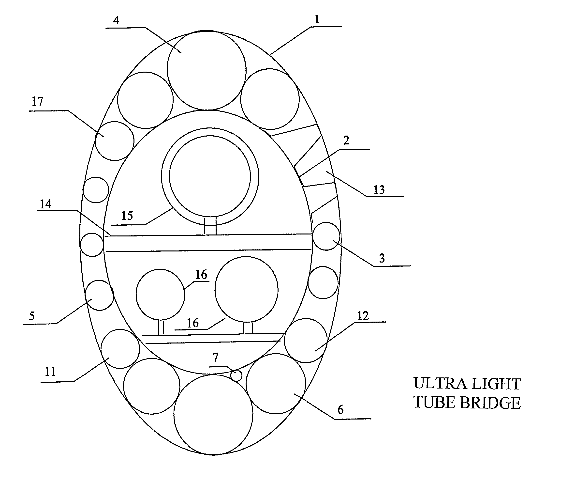
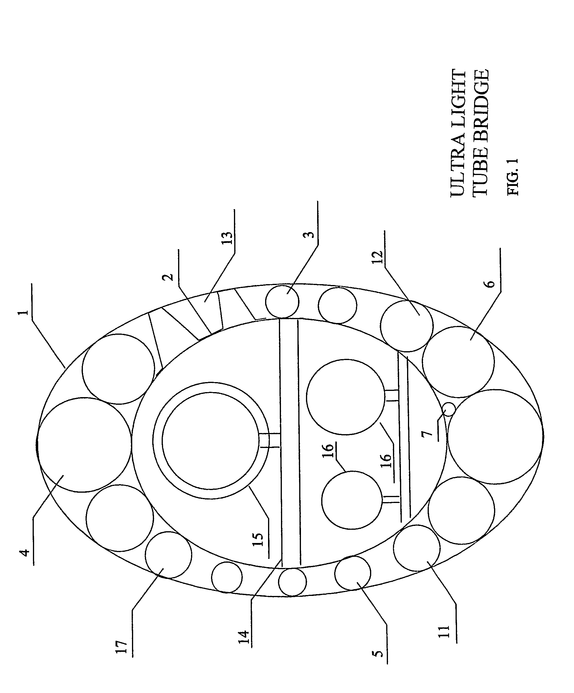
[0018]FIG. 1 shows a pipe bridge that comprises an oval outer skin tube 1 and circular inner tube 2. The distance between outer tube 1 and inner tube 2 is thus greater at the tips of the oval than at the sides thereof. This makes it possible to place pipes of different diameters in the space between the inner and outer tube. At the upper part of the pipe bridge wherein the distance between the inner and outer tube is greatest, is placed a integrated gas pipe 4 having a large diameter. The space between the tubes 1, 2 becomes smaller towards the midpoint of the oval of the outer tube 1. Simultaneously the diameter of pipes placed in the space diminishes accordingly. In this embodiment the pipes include liquid pipes 3, air pipes 5, a pneumatic transfer line 6, a channel for automation cables 11, a channel for electric cables 12 and pipe for removal of condensed water 9 and finally, integrated process pipes 17. Further, a space 13 is formed between the inner and outer tube for a mainte...


PUM


Abstract

The bridge is constructed of one inner tube and an outer tube surrounding the inner tube. The inner and outer tube are joined to each other by connecting pipes welded to the outer surface of the inner tube and to the inner surface of the outer tube so that the inner tube and the outer tube are connected to each other through said connecting pipes whereby a rigid composite structure is formed. The tubes and pipes are preferably laser welded to each other, preferably by a continuous seam.

Description

[0001]This is a national stage application filed under 35 USC 371 based on International Application No. PCT / FI2006 / 000218 filed Jun. 20, 2006.[0002]The present invention relates to a method for manufacturing a ultralight steel bridge for forming a passage for materials, electricity and communications lines as well as personnel among others.[0003]The invention relates also to a bridge manufactured by the method.BACKGROUND OF THE INVENTION[0004]At the moment walking bridges, pipe bridges and conveyor bridges include a supporting frame and walls, floor and roof that cover the frame. Pipes, walking paths, cables and such are located inside the bridge and require further supporting structures that are used for mounting these to the frame of the bridge. Thus the frame has to support all the weight of the covering structures and effective elements as well as their supporting structures, whereby the supporting frame has to be very strong and heavy. A heavy structure further requires a supp...

Claims


Application Information

Patent Timeline
Patent Type & Authority Patents(United States)
IPC IPC(8): E01D21/00
CPCE01D1/00E01D15/14E02D29/067E01D18/00E01D2101/30E01D2/00
Inventor MIETTINEN, ENSIO JOHANNES
Owner MIETTINEN ENSIO JOHANNES
Why Eureka
Try Eureka