
Hybrid trailer system

a hybrid trailer and trailer technology, applied in the direction of braking system, capacitor propulsion, electric devices, etc., can solve the problems of not having the room to add a new or retrofit hybrid system, engine emitting large amounts of pollutants, and conventional semi-tractors do not have the space to add a hybrid system. , to achieve the effect of easy retrofitting into new or used trailers and low maintenan

Inactive Publication Date: 2012-07-10
DEGRAVE KEN +1
View PDF18 Cites 74 Cited by
  • Summary
  • Abstract
  • Description
  • Claims
  • Application Information

AI Technical Summary

Benefits of technology

The system allows for quieter braking, improved load stabilization, reduced wear on brakes and drive trains, extended equipment lifespan, and enhanced safety by efficiently managing energy storage and usage, eliminating the need for loud 'jake braking' and improving trailer response to traffic changes.

Problems solved by technology

In particular, there is no such assembly in a package that can be easily retrofit into new or used trailers, including semi-trailers, that is completely self-contained, and can be connected to an ordinary, unmodified semi-tractor.
Conventional semi-tractors do not have the room to add a new or retrofit hybrid system.
When an ICE tractor accelerates from rest, the engine emits large amounts of pollutants.
When the tractor decelerates, the brakes from the tractor and trailer must dissipate large amounts of kinetic energy through heat or by “jake braking,” the process by which the energy is pushed back through the ICE causing large amounts of noise.
Current tractor-trailer systems also have a lower response time to traffic flow changes due to the heavy load being hauled.
A tractor's ICE can only provide so much power for quick acceleration.
ABS only helps the trailer wheels get better traction during deceleration, however.
The use of batteries to power an electric motor on a semi-trailer is known, but a problem with the use of batteries is the high amount of power that these devices must absorb in a short period of time during braking.
Batteries can hold large amounts of power, in general, but they charge and discharge at slow rates.
Increasing the charge and discharge rates results in a shortened lifespan of the battery.
In addition, all batteries have a limited life span, and need to be replaced periodically.
Batteries also contain corrosive elements that can spill if damaged.

Method used


Image

  • Hybrid trailer system
  • Hybrid trailer system
  • Hybrid trailer system

Examples


Embodiment Construction

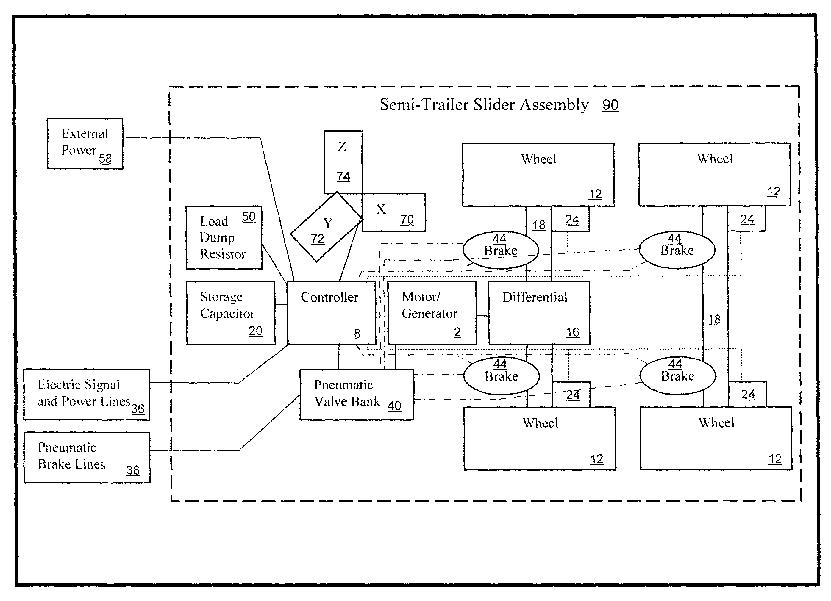
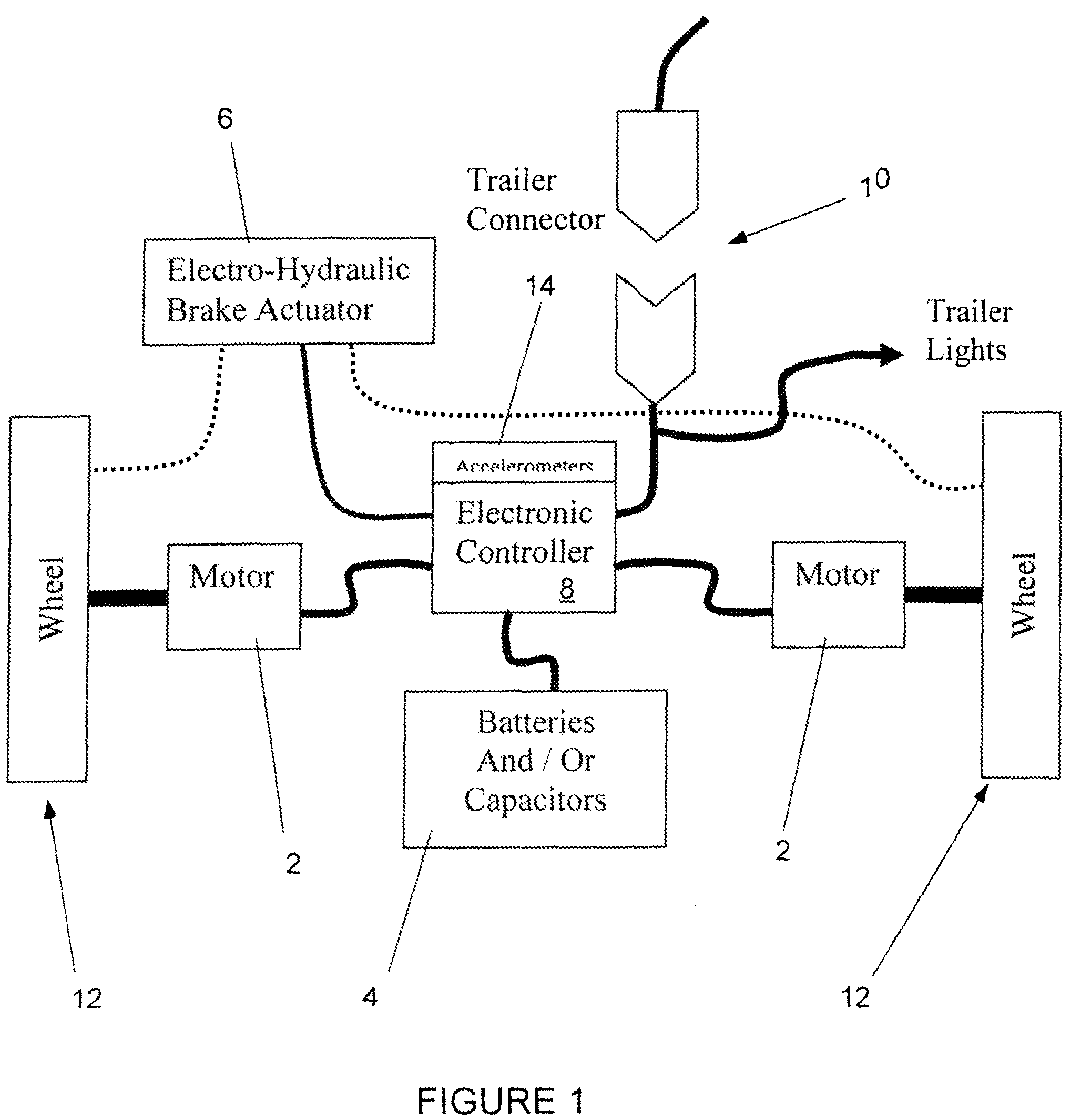
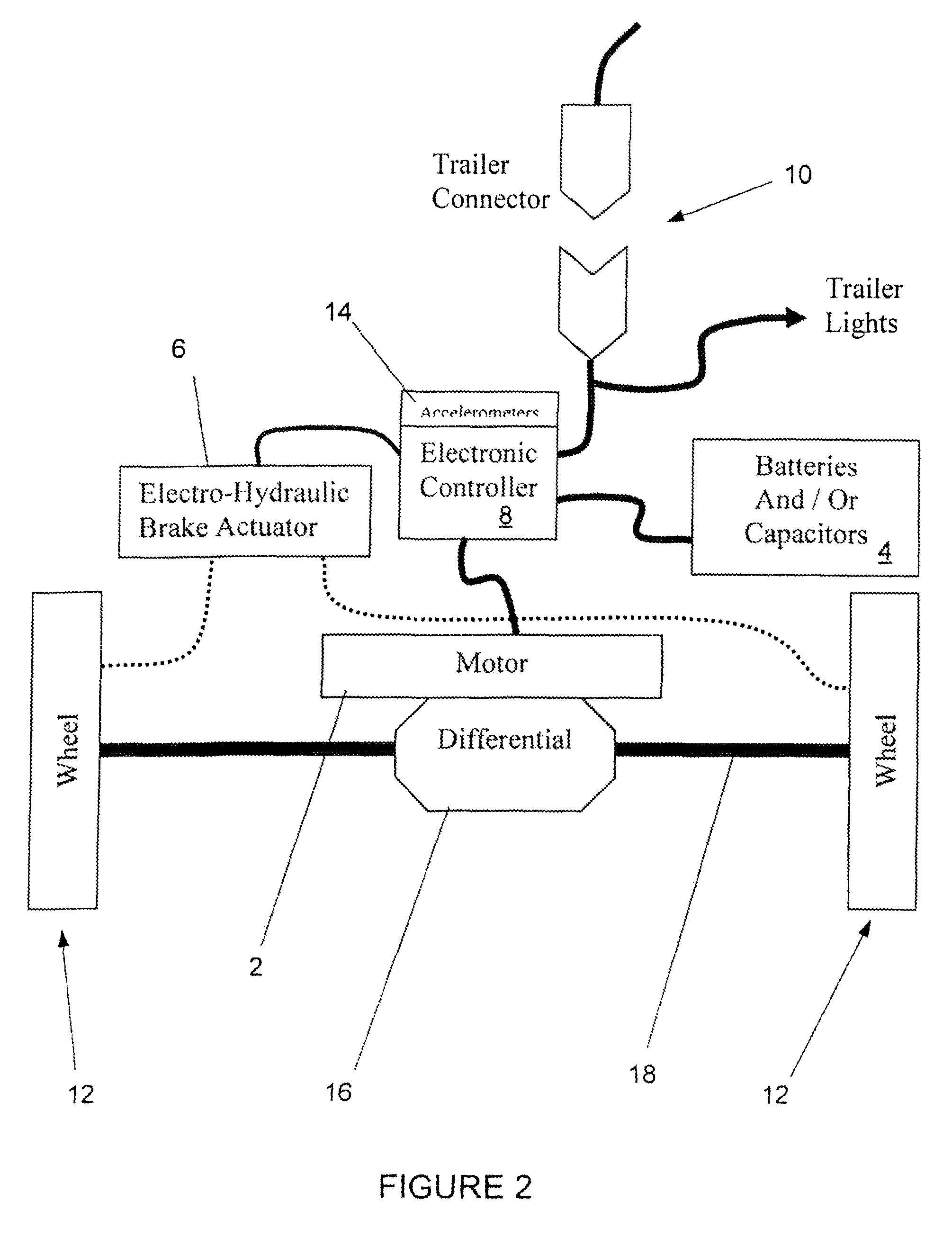
[0021]The present invention is a system and apparatus for a hybrid trailer. FIG. 1 shows an exemplary embodiment of the present invention comprising two motors 2 in electrical connection with an energy storage system 4, a brake actuator 6, and an electronic controller 8. The electronic controller 8 monitors the trailer connector 10 for a variety of signals for operator action, including but not limited to braking, turn signals, and back-up signals. The trailer connector 10 also can monitor in real-time a variety of trailer operations, including but not limited to the speed of one or more trailer wheels 12, torque, and one or more accelerometers 14 or similar sensors 15. The energy storage system 4 may comprise one or more energy storage devices, including but not limited to batteries, capacitors 20, or some combination thereof.

[0022]Capacitors 20 as means of energy storage have several advantages. Capacitors can store energy at fast rates. The regenerative energies from a trailer, i...


PUM


Abstract

A system and related method for a regenerative braking system on a towed vehicle, such as a trailer or semi-trailer. The system provides power and braking to the respective trailer wheels, as needed, to help stabilize the trailer. Power is regenerated during braking. While batteries may be used to store the energy, the system also may use capacitive storage units, which charge and discharge large amounts of energy at a fast rate. A multiple-axis sensor system in conjunction with wheel sensors, load sensors, and proportional control of the brakes and motor power to the axles and wheels, is used to achieve superior load stabilization. The invention can be easily retrofit into new or used trailers, and is self-contained with low maintenance.

Description

[0001]This application claims benefit of, and priority to, U.S. Provisional Patent Application No. 60 / 883,215, filed Jan. 3, 2007, U.S. Provisional Application No. 60 / 883,219, filed Jan. 3, 2007, and U.S. Provisional Patent Application No. 60 / 950,014, filed Jul. 16, 2007, each entitled “HYBRID TRAILER SYSTEM.” The complete specifications, drawings, attachments and disclosures of U.S. Provisional Patent Application Nos. 60 / 883,215, 60 / 883,219 and 60 / 950,014 are incorporated herein by specific reference.FIELD OF INVENTION[0002]This invention relates to a hybrid trailer system and apparatus. More particularly, the invention relates to a system and apparatus for placing one or more motors on a trailer to assist in operation of the trailer.BACKGROUND OF THE INVENTION[0003]At present, there are no trailer axle assemblies known being produced that can collect kinetic energy during deceleration of the vehicle, and retrieve that energy for acceleration. In particular, there is no such assemb...

Claims


Application Information

Patent Timeline
Patent Type & Authority Patents(United States)
IPC IPC(8): B60L11/00B62D61/12
CPCB60L7/08B60L7/18B60L11/005B60L11/1816B60L15/20B60T8/1708B60L7/10Y02T10/7275B60L2200/28B60L2220/18B60L2220/44B60L2260/28B60T2270/604Y02T10/7005Y02T10/7022Y02T90/14B62D59/04B60L50/40B60L53/14Y02T10/64Y02T10/70Y02T10/7072Y02T10/72
Inventor DEGRAVE, KENMCMILLAN, WILLIAM
Owner DEGRAVE KEN
Learn More