
Roof construction of a vehicle body

a technology for roof modules and vehicle bodies, which is applied in the direction of vehicle bodies, monocoque constructions, superstructure sub-units, etc., can solve the problems of breaking the bond seam between the roof module frame and the body, and reducing the overall rigidity of the passenger cabin. , to achieve the effect of reducing cost and effor

Active Publication Date: 2012-07-10
THYSSENKRUPP STEEL EURO AG
View PDF23 Cites 11 Cited by
  • Summary
  • Abstract
  • Description
  • Claims
  • Application Information

AI Technical Summary

Benefits of technology

[0004]Based on the above, an aspect of the present invention is to propose a motor vehicle body which is accident-optimized and which with little cost and effort prevents the roof module from breaking away.
[0006]It has been shown that the outer roof frame, which in conjunction with the inner roof frame is often described as a side member, can be used as a locking element in such a way that in a crash locking with the lateral roof module frame occurs and breaking away of the roof module is prevented. Since the outer roof frame of the motor vehicle body is used as a locking element, a retaining element is no longer necessary on the roof module and the labor costs for producing an accident-optimized motor vehicle body in the roof area are considerably reduced. Further advantages result from the fact that the behavior of the body in the event of a side impact can be specifically controlled via the geometrical cross-sectional shape of the outer roof frame.
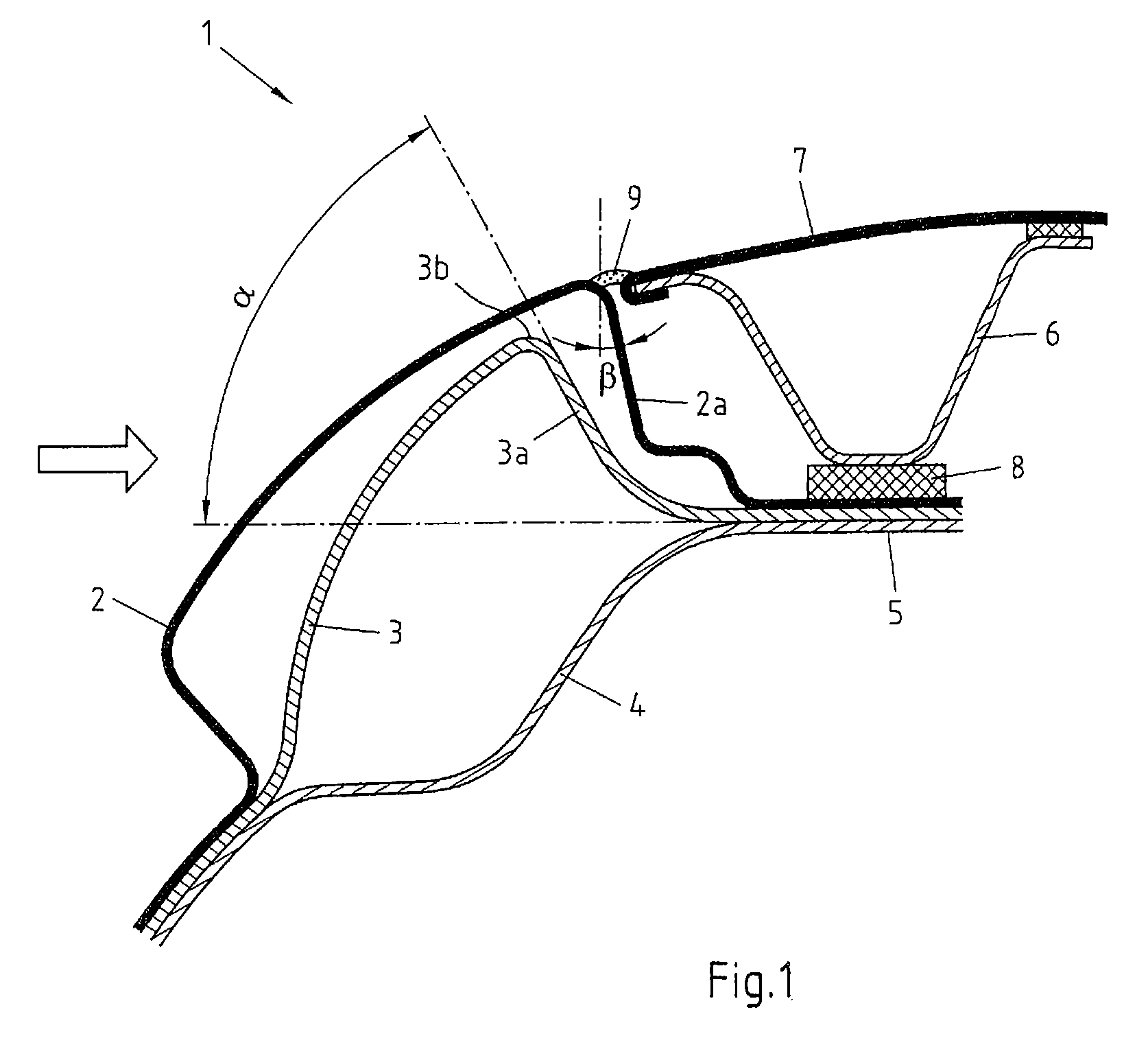
[0007]According to a first embodiment of a body according to the invention, one part of the outer roof frame of the body extends above the weld flange, wherein one area of the outer roof frame sloping away to the weld flange occupies an angle of more than 45° to the plane of the weld flange. This outer roof frame embodiment demonstrates a particularly simple possibility for designing the outer roof frame as a locking element. In the event of a side impact, this design prevents the outer roof frame from sliding past the roof module frame and the connection between body and roof module frame from loosening. Breaking away of the roof module is thereby prevented.
[0008]According to a subsequent, refined embodiment of the body according to the invention, the behavior of the body in an accident is further improved by the highest point of the part of the outer roof frame extending above the weld flange having a vertical distance from the weld flange of at least 40% of the vertical distance between the highest point of the outer skin and the weld flange.
[0009]The locking of the outer roof frame with the roof module support can be further strengthened by the angle of an area of the outer roof frame sloping away to the weld flange being more than 90° to the plane of the weld flange and forming an undercut with the weld flange. The result obtained through this is that the outer roof frame grips hard together with the outer skin and the roof module frame when the body is deformed, so that particularly secure locking is produced between the roof module frame and the body.
[0011]Preferably, the outer skin of a subsequent, refined embodiment of the body according to the invention occupies an angle of 1° to 10° to the vertical in an area sloping away to the weld flange. This angle enables the body to be used both for a roof module and for a laser-soldered roof The angle also ensures that, on the one hand, an edge is formed between laser-soldered roof and body which enables the laser solder to run in between the contact surface of the roof skin and body and enables degassing of the laser solder, so that a clean laser-soldered seam is formed. On the other hand, roof modules can be applied more easily during final assembly using this embodiment of the body.

Problems solved by technology

With bonded roof modules there is, in principle, the danger that the bond seam between the roof module frame and the body will break and that the roof module will break away from the motor vehicle.
Breaking away of the roof must, however, be avoided, since then the overall rigidity of the passenger cabin decreases considerably and its properties in the case of deformation caused by an accident are impaired considerably.
Attaching the retaining element to the roof module is, however, labor-intensive.
Moreover, the retaining elements impede the use of a roof module frame which is required to provide reinforcement.

Method used


Image

  • Roof construction of a vehicle body
  • Roof construction of a vehicle body
  • Roof construction of a vehicle body

Examples


Embodiment Construction

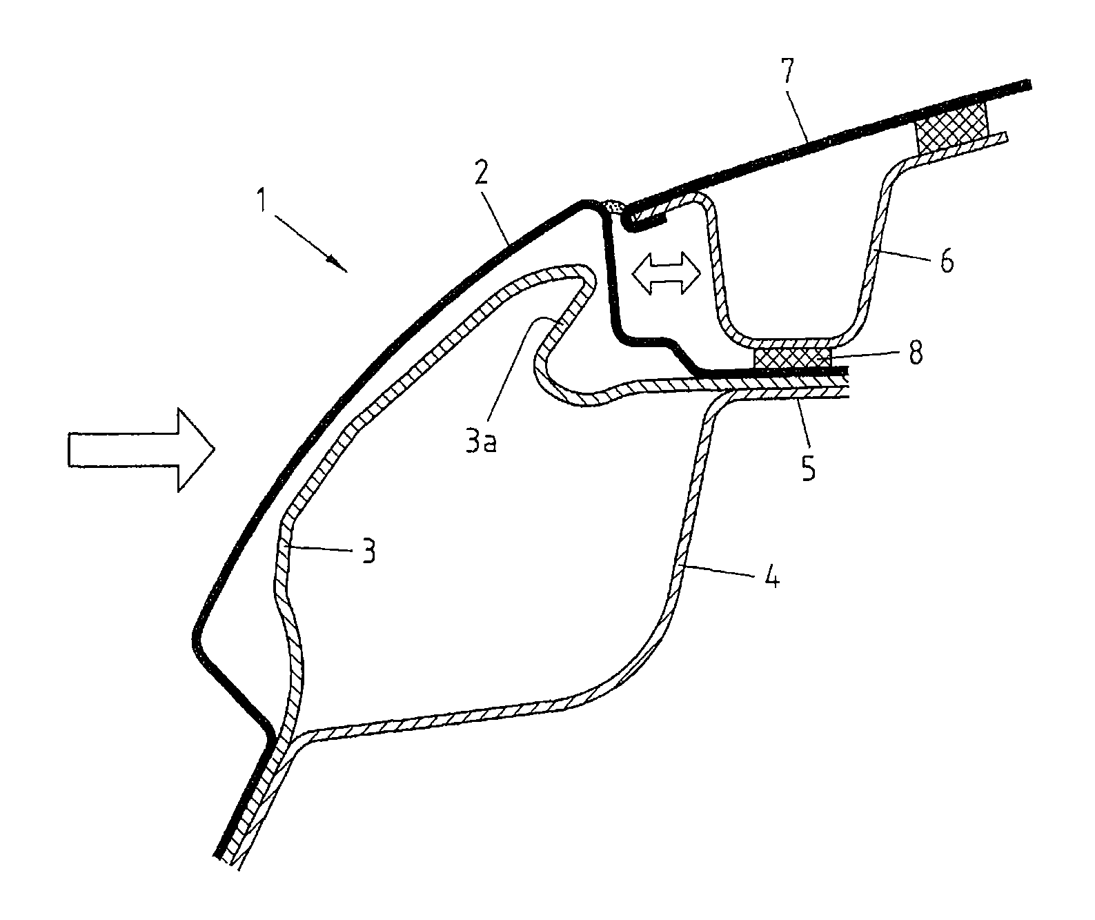
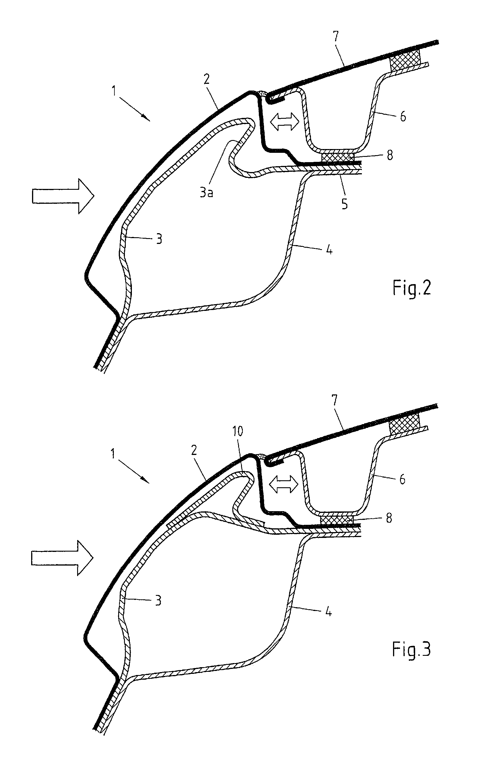
[0019]FIG. 1 now shows in a schematic sectional view the lateral roof area 1 of an exemplary embodiment of a body according to the invention. This has an outer skin 2, an outer roof frame 3 and an inner roof frame 4. The outer skin 2, the outer roof frame 3 and the inner roof frame 4 are connected to one another by means of a weld flange 5. The outer skin is typically a very thin sheet having a thickness of approximately 0.7 mm, whereas the outer roof frame 3 and the inner roof frame 4 are predominantly produced from high-strength or ultra high-strength materials, for example from a type 22MnB5 steel alloy, and with sheet thicknesses of 0.8 mm to 2 mm provide the required strength for the body.

[0020]The outer roof frame 3, which together with the inner roof frame 4 form the side member of the body, is formed as a locking element in the present exemplary embodiment, which in the case of deformation by a force in the direction of the arrow, i.e. in the case of a side impact, locks wit...


PUM


Abstract

A body of a motor vehicle includes a lateral roof region that has an outer skin, an outer roof frame, and an inner roof frame, wherein the outer roof frame is arranged under the outer skin and the inner roof frame is arranged under the outer roof frame, and the outer skin, the outer roof frame, and the inner roof frame have a common welded flange, by means of which the outer skin and the outer and inner roof frames are connected to one another, and which is configured to receive an adhesive layer for a roof module having a roof module frame. An aspect of the invention is to provide an accident-optimized vehicle body at little expense that prevents a tearing off of the roof module, and is achieved in that the outer roof frame of the body is configured as a locking element for the roof module frame.

Description

CROSS-REFERENCE TO RELATED APPLICATIONS[0001]This application is a National Phase Application of International Application No. PCT / EP2008 / 061698, filed on Sep. 4, 2008, which claims the benefit of and priority to German patent application no. DE 10 2007 042 277.8-56, filed on Sep. 6, 2007. The disclosures of the above applications are incorporated herein by reference in their entirety.FIELD OF THE INVENTION[0002]The invention relates to a body of a motor vehicle, in which the lateral roof area has an outer skin, an outer roof frame and an inner roof frame, wherein the outer roof frame is arranged under the outer skin and the inner roof frame is arranged under the outer roof frame, and the outer skin, the outer roof frame and the inner roof frame have a common weld flange, by means of which the outer skin, the outer and the inner roof frames are connected to one another and which is designed to accommodate an adhesive layer for a roof module having a roof module frame.BACKGROUND[0003...

Claims


Application Information

Patent Timeline
Patent Type & Authority Patents(United States)
IPC IPC(8): B62D25/06
CPCB62D25/06
Inventor GRUNEKLEE, AXELPATBERG, LOTHARSCHMITZ, KAILOSCH, ALFREDSTEGMEYER, RALF
Owner THYSSENKRUPP STEEL EURO AG
Learn More